Improved hydrofoil device

A component and hydrodynamic technology, applied to ship components, using hydrofoils to act on the surrounding water surface to reduce ship motion, rotary propellers, etc., can solve problems such as poor component efficiency, low pressure in the separation area, and complexity

Inactive Publication Date: 2003-09-17
VEEM工程集团有限公司
View PDF1 Cites 1 Cited by
  • Summary
  • Abstract
  • Description
  • Claims
  • Application Information

AI Technical Summary

Problems solved by technology

It is the pressure drag component associated with this low pressure region that causes this poor component efficiency
[0008] Similar components are more complex when used in water due to the presence of multiphase flows, i.e. liquid and gas
Although a pressure increase can occur in the front of the part, the separation area formed behind the part is very low pressure and creates air pockets

Method used


Image

  • Improved hydrofoil device
  • Improved hydrofoil device
  • Improved hydrofoil device

Examples


Embodiment Construction

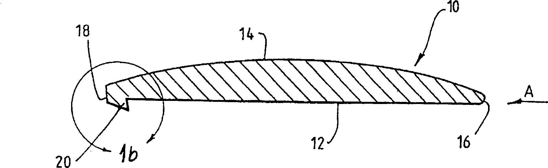
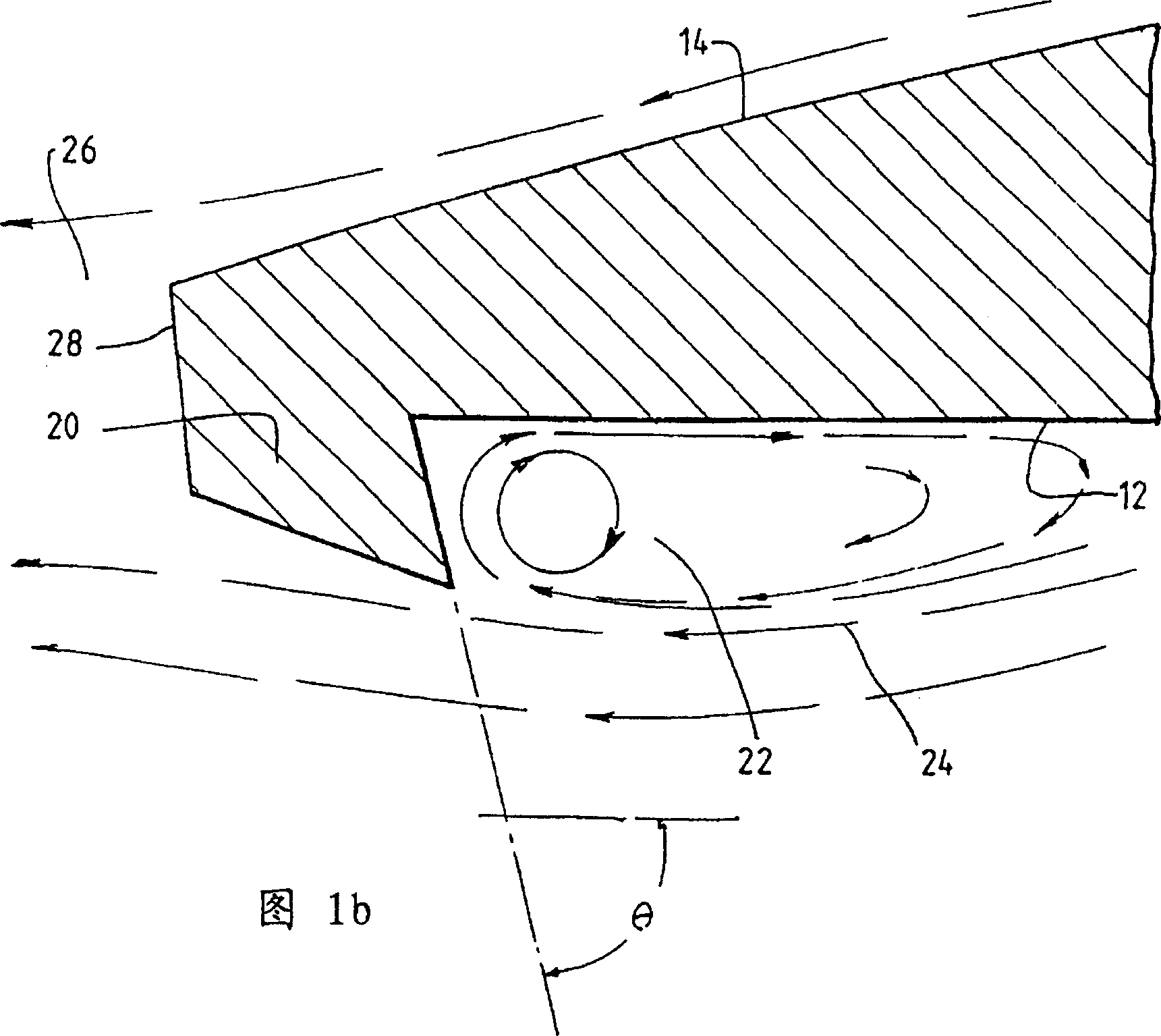
[0042] As shown in FIG. 1, a first embodiment of an improved hydrofoil 10 according to the present invention includes a first surface 12 which is subjected to a pressure greater than the surrounding local pressure. The second surface 14 is located on the other side of the hydrodynamic component. When water flows through the first surface and the second surface from the front edge 16 to the rear edge 18 of the component 10 in the direction indicated by arrow A, the pressure on the second surface 14 is generally Lower pressure than the first surface 12. A protrusion 20 is provided adjacent the trailing edge 18 , thereby forming a surface discontinuity on the first surface 12 . As can be seen more clearly from FIG. 1 b , the protrusion 20 forms an included angle θ of about 90° with the upstream direction of the hydrodynamic component, so that the water flow on the first surface 12 can turn back by itself. For this reason, the included angle θ is preferably slightly smaller than ...


PUM


Abstract

A hydrodynamic component may be used as a hydrofoil, a propeller blade, or the like. In the water flow, less pressure is generated on the second surface (94) of the component than on the first surface (96). Near the trailing edge of the first surface is provided a protrusion forming an adjustable spoiler (98). The raised surface forms an included angle less than or equal to 90° with the upstream direction. At this point the flow can turn back on itself, increasing the local pressure on the first surface. A second protrusion may be provided at the leading edge of the second surface (94) to facilitate flow separation at that location. Air is provided at each protrusion to allow natural ventilation when the water flow pressure is below atmospheric pressure.

Description

technical field [0001] The present invention relates to an improved hydrofoil device such that lift is primarily generated by a local pressure increase above the pressure of the local free stream or ambient pressure. The invention relates particularly, but not exclusively, to an improved hydrodynamic component for watercraft, such as control surfaces such as hydrofoils, blades, rudders, and seaplanes. Background technique [0002] As used in this specification, the term "hydrodynamic component" refers to a physical structure designed to generate lift while passing through water; similarly, the term "aerodynamic component" refers to a similar structure in air. Hydrodynamic components can be used as dynamic supports, such as wings, control surfaces such as rudders, propellers, pumps and propellers such as water turbines. However, the principles behind hydrofoils are similar across applications. [0003] Similar to aerodynamics, hydrodynamics create lift by changing the veloc...

Claims


Application Information

Patent Timeline
Patent Type & Authority Patents(China)
IPC IPC(8): B63B1/24B63B1/28B63H1/26B63B39/06B63H25/38
CPCB63B1/248B63B1/288B63B39/06B63B2001/325B63H1/26B63H25/382Y02T70/10
Inventor 安东尼·R·埃尔姆斯
Owner VEEM工程集团有限公司
Why Eureka
Try Eureka