
Elevator framework and corridor structure and installation method thereof

A technology for skeletons and corridors, which is applied to elevators, transportation and packaging, and building construction in buildings. It can solve problems such as low connection accuracy, low construction efficiency, and low structural strength, and achieve high support reliability and improved The effect of bearing capacity and the stability of the connection structure

Active Publication Date: 2017-09-15
惠州市惠发电梯工程有限公司
View PDF4 Cites 0 Cited by
  • Summary
  • Abstract
  • Description
  • Claims
  • Application Information

AI Technical Summary

Problems solved by technology

[0006] In order to solve the technical problems of low construction efficiency, low connection precision and low structural strength in the construction of the elevator skeleton and corridor structure in the prior art, the present invention aims to provide an elevator skeleton and connection with reliable connection, high precision and short installation period. corridor structure

Method used


Image

  • Elevator framework and corridor structure and installation method thereof
  • Elevator framework and corridor structure and installation method thereof
  • Elevator framework and corridor structure and installation method thereof

Examples


Embodiment 1

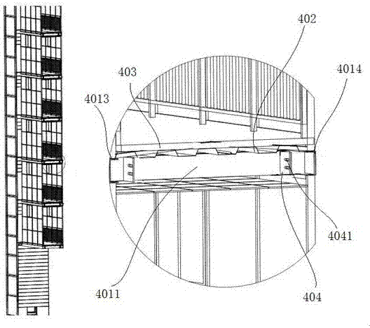
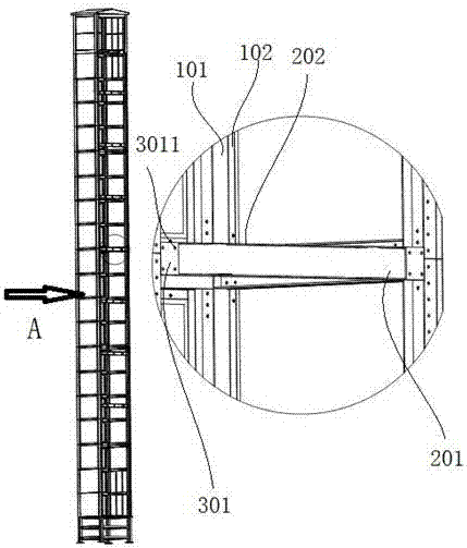
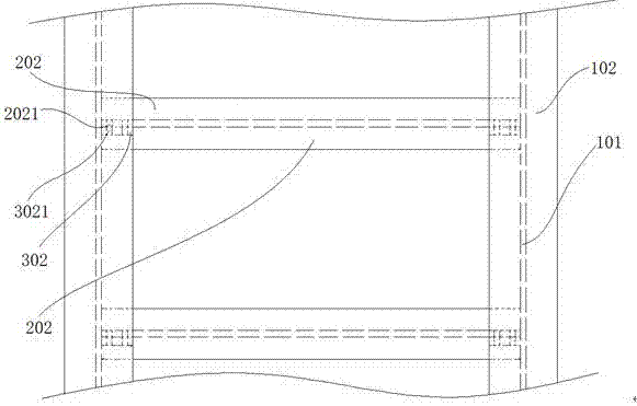
[0046] Such as Figure 1-5 As shown, this embodiment provides an elevator frame and corridor structure, including: elevator frame: including longitudinal H-shaped steel and transverse H-shaped steel, the longitudinal H-shaped steel includes a longitudinal web 101 and two longitudinal wings 102 parallel to each other, two A longitudinal web 102 is connected by a longitudinal web 101, and the longitudinal web 101 is vertically arranged between two longitudinal webs 102; the transverse H-shaped steel includes a transverse web 201 and two transverse webs 202 parallel to each other, and the two transverse Flanges 202 are connected by transverse webs 201, and transverse webs 201 are vertically arranged between two transverse webs 202, and transverse webs 201 are provided with web through holes; mounting plate: includes wing plate mounting plate 301 and web installation Plate 302, the wing plate mounting plate 301 is vertically connected to the outer surface of the longitudinal wing ...

Embodiment 2

[0056] This embodiment provides an elevator frame and corridor structure, including: elevator frame: including longitudinal H-shaped steel and transverse H-shaped steel, the longitudinal H-shaped steel includes a longitudinal web 101 and two longitudinal wing plates 102 parallel to each other, and two longitudinal wing plates The plates 102 are connected by a longitudinal web 101, which is vertically arranged between two longitudinal wings 102; the transverse H-shaped steel includes a transverse web 201 and two parallel transverse wings 202, and the two transverse wings 202 Connected by a transverse web 201, the transverse web 201 is vertically arranged between two transverse wing plates 202, and the transverse web 201 is provided with a web through hole; the mounting plate: includes a wing plate mounting plate 301 and a web mounting plate 302, The wing plate mounting plate 301 is vertically connected to the outer side of the longitudinal wing plate 102, and the wing plate moun...

Embodiment 3

[0058]This embodiment provides an elevator frame and corridor structure, including: elevator frame: including longitudinal H-shaped steel and transverse H-shaped steel, the longitudinal H-shaped steel includes a longitudinal web 101 and two longitudinal wing plates 102 parallel to each other, and two longitudinal wing plates The plates 102 are connected by a longitudinal web 101, which is vertically arranged between two longitudinal wings 102; the transverse H-shaped steel includes a transverse web 201 and two parallel transverse wings 202, and the two transverse wings 202 Connected by a transverse web 201, the transverse web 201 is vertically arranged between two transverse wing plates 202, and the transverse web 201 is provided with a web through hole; the mounting plate: includes a wing plate mounting plate 301 and a web mounting plate 302, The wing plate mounting plate 301 is vertically connected to the outer side of the longitudinal wing plate 102, and the wing plate mount...


PUM


Abstract

The invention discloses an elevator framework and corridor structure. The structure comprises an elevator framework, a installation plate, a corridor bottom frame, a corridor body and a connecting part; the elevator framework comprises longitudinal H-shaped steel and transverse H-shaped steel; the installation plate comprises a wing plate installation plate and a web plate installation plate, wherein the wing plate installation plate is vertically connected to the outer side surface of a longitudinal wing plate, a first installation hole is formed in the position, corresponding to a web plate through hole, of the wing plate installation plate, the wing plate installation plate is connected to a transverse web plate through bolts, the web plate installation plate is vertically connected to a longitudinal web plate, a second installation hole corresponding to the web plate through hole is formed in the web installation plate, and the web plate installation plate is connected to the transverse web plate through bolts; the corridor bottom frame comprises a rectangular frame body, wherein the rectangular frame body comprises a right side plate, a front side plate, a left side plate and a rear side plate which are sequentially connected in an end-to-end mode to form a rectangle; the corridor body is fixedly connected to the rectangular frame; and the connecting part is used for being connected to the corridor bottom frame and the elevator framework. The elevator framework and corridor structure is reliable in connection, high in precision and short in installation period.

Description

technical field [0001] The invention relates to a connection structure, in particular to an elevator frame and corridor structure and an installation method thereof. Background technique [0002] Elevator is mainly composed of traction machine (winch), guide rail, counterweight device, safety device (such as speed limiter, safety gear and buffer, etc.), signal control system, car and hall door, etc. These parts are respectively installed in the hoistway and machine room of the building. Steel wire rope friction transmission is usually used. The wire rope goes around the traction sheave, and the two ends are respectively connected to the car and the counterweight. The motor drives the traction sheave to lift the car up and down. With the popularity of automation equipment, elevators are widely used in life and production. [0003] Before the installation of the lift elevator, it is necessary to build the elevator skeleton, and the realization of the function of the lift ele...

Claims


Application Information

Patent Timeline
Patent Type & Authority Applications(China)
IPC IPC(8): B66B11/00E04B1/00E04B1/38
CPCE04B1/0046B66B11/00E04B1/388
Inventor 杨光星杨柳强
Owner 惠州市惠发电梯工程有限公司
Learn More