Connecting form, form erecting structure and form erecting method
A formwork and connecting part technology, which is applied in the direction of formwork/formwork/work frame, connection parts of formwork/formwork/work frame, building structure, etc., can solve the problem of increasing construction strength, increasing construction cost, long service life, etc. question
- Summary
- Abstract
- Description
- Claims
- Application Information
AI Technical Summary
Problems solved by technology
Method used
Image


Examples
Embodiment 1
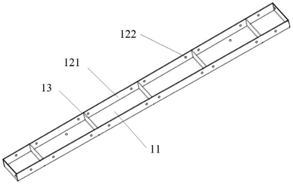
[0039] This embodiment provides a connection template 1, such as Figure 1 to Figure 4 As shown, it includes: a board body 11 and two connecting parts 121 . In this embodiment, the transverse section of the plate body 11 is a right-angled trapezoid, and the connecting portion 121 is arranged on the height and side of the plate body 11, and the connecting portion 121 is extended along the length direction, and the connecting portion 121 is used for connecting with the standard template 2 connect.
[0040] Specifically, in this embodiment, the connecting portion 121 is a bent plate disposed on the side of the board body, specifically disposed on the side where the height of the right-angled trapezoid is located and the side where the hypotenuse of the right-angled trapezoid is located. In this embodiment, a connecting hole 122 is provided on the bent plate, and the connecting hole 122 is used for connecting with the standard formwork 2 . The connecting hole 122 on the connecti...
Embodiment 2
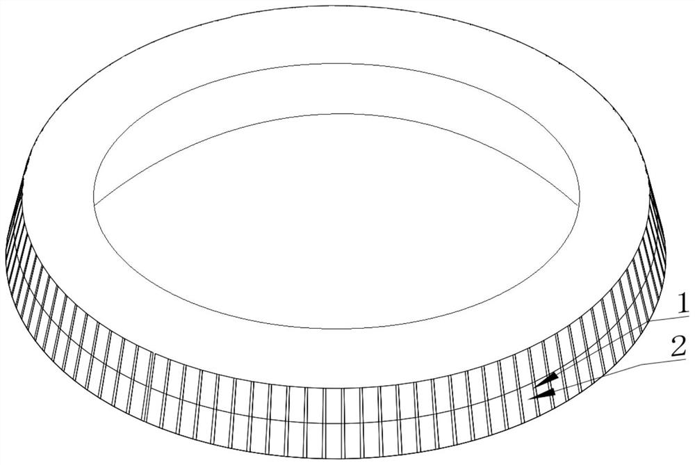
[0051] This embodiment provides a supporting formwork structure, including: a standard formwork 2 and the connection formwork 1 provided in Embodiment 1, the standard formwork 2 and the connection formwork 1 are arranged at intervals to form the side of the formwork support circular frustum.
[0052] Specifically, in this embodiment, locking the connecting template 1 and the standard template 2 is realized by a locking member. Specifically, the locking member is a U-shaped card, and the U-shaped part of the U-shaped card passes through the connection hole 122 and the communication hole on the standard template 2 in sequence, and the two ends of the U-shaped part are locked by the locking part.
[0053] The form support structure in this embodiment also includes a support frame arranged outside the round platform of the form support, specifically, the support frame is a scaffold. For example, a scaffold pipe with a diameter of 48.3mm is used for assembly, and the connection bet...
Embodiment 3
[0055] The present embodiment provides a kind of formwork method, adopts the formwork structure in embodiment 2, comprises the following steps:
[0056] Fabricate: fabricate connection template 1;
[0057] Connection: connect the two sides of several connecting templates 1 with the two sides of the standard template 2 to form the sides of the round platform of the formwork. Specifically, connect the side connecting parts 121 of the connection formwork 1 with the sides of the standard formwork 2 through U-shaped cards, and set the first layer of formwork round table and the second layer of support from bottom to top according to the specific number of layers. Die round table. Connect two adjacent layers of connection templates 1, and connect two adjacent layers of standard templates 2 to each other. Finally, the support frame and the round platform of the formwork are locked and connected to each other through the connecting piece. Afterwards, concrete pouring is carried out...
PUM
| Property | Measurement | Unit |
|---|---|---|
| Diameter | aaaaa | aaaaa |
| Height | aaaaa | aaaaa |
Abstract
Description
Claims
Application Information
 - R&D
- Intellectual Property
- Life Sciences
- Materials
- Tech Scout
- Unparalleled Data Quality
- Higher Quality Content
- 60% Fewer Hallucinations
Browse by: Latest US Patents, China's latest patents, Technical Efficacy Thesaurus, Application Domain, Technology Topic, Popular Technical Reports.
© 2025 PatSnap. All rights reserved.Legal|Privacy policy|Modern Slavery Act Transparency Statement|Sitemap|About US| Contact US: help@patsnap.com