

Air coupling ultrasonic detection method for vertical honeycomb spliced interfaces
An air-coupling and ultrasonic testing technology, which is applied to the analysis of solids using sound waves/ultrasonic waves/infrasonic waves, material analysis using sound waves/ultrasonic waves/infrasonic waves, and measuring devices. It can solve the problems of low detection accuracy, increased manufacturing risks, and multi-layer honeycomb Inaccurate detection results of the sandwich structure and other problems, to achieve the effects of high detection accuracy, small attenuation, and low detection difficulty
- Summary
- Abstract
- Description
- Claims
- Application Information
AI Technical Summary
Problems solved by technology
Method used
Image

Examples
Embodiment Construction
[0026] The technical solutions of the present invention will be further described below in conjunction with the accompanying drawings and through specific implementation methods.
[0027] In describing the present invention, it is to be understood that the terms "upper", "lower", "front", "rear", "left", "right", "vertical", "horizontal", "top", The orientation or positional relationship indicated by "bottom", "inner", "outer", etc. is based on the orientation or positional relationship shown in the drawings, and is only for the convenience of describing the present invention and simplifying the description, rather than indicating or implying the referred device Or elements must have a certain orientation, be constructed and operate in a certain orientation, and thus should not be construed as limiting the invention.
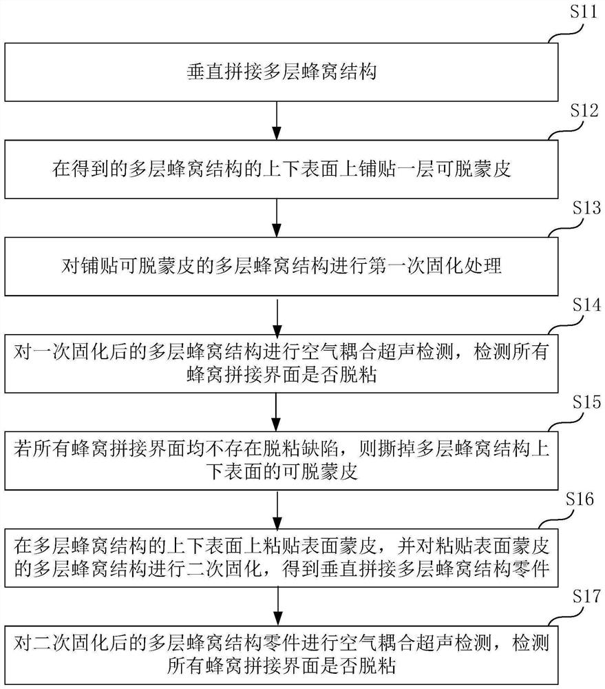
[0028] see figure 1 , the vertical honeycomb splicing interface air-coupled ultrasonic detection method of an embodiment comprises the following steps:
[002...
PUM
 Abstract
Description
Claims
Application Information