
Display device and method for positioning position information of display device

A display device and position information technology, applied in the direction of digital output to display equipment, input/output process of data processing, instruments, etc., can solve the problem of inability to correctly process video signal streams, small transmission distance, and conventional wiring schemes that cannot meet new requirements. The requirements of the application scene and other issues

Pending Publication Date: 2020-12-29
UNILUMIN GRP
View PDF1 Cites 0 Cited by
  • Summary
  • Abstract
  • Description
  • Claims
  • Application Information

AI Technical Summary

Problems solved by technology

[0011] (4) The signal is concentrated between the display module cabinet and its adjacent display module cabinet, and does not involve the transmission of the entire screen, and the transmission distance is relatively small
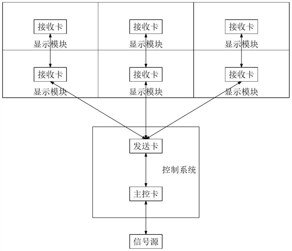
[0014] At present, commonly used display signal processing schemes such as figure 1 As shown (such as the control architecture of the all-in-one display device, application number 201910900156.8), the signal flow direction of the display screen is the vertical direction, and the signal cannot be transmitted horizontally
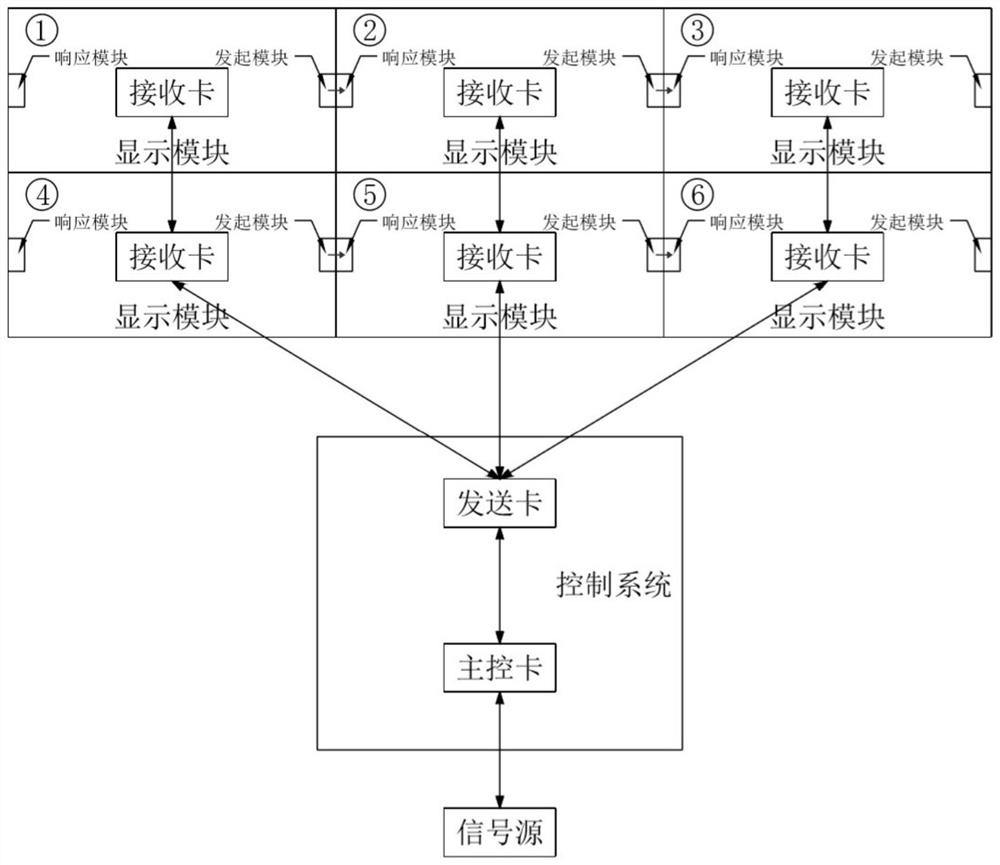
For the display, figure 1 The wiring scheme shown has already met the transmission requirements of most signals, but with the development of the intelligent setting mode of the display screen, in new application scenarios, it is required that the box can realize simple communication in the horizontal direction, such as accurately positioning the positional relationship feedback to the control system, figure 1 The conventional wiring scheme can no longer meet the needs of new application scenarios
[0015] For the control system of the display screen, the code of each module and the number of modules are relatively easy to determine, but it is difficult to determine the position information of each display module. Generally, manual debugging is required to determine one by one, and then enter the system, otherwise the system cannot handle it correctly. The video signal flow makes the content played by the module look like a jigsaw puzzle, which cannot form a complete whole

Method used


Image

  • Display device and method for positioning position information of display device
  • Display device and method for positioning position information of display device
  • Display device and method for positioning position information of display device

Examples


Embodiment Construction

[0036] In order to make the technical problems, technical solutions and beneficial effects to be solved by the present invention clearer and clearer, the present invention will be further described in detail below in conjunction with the accompanying drawings and embodiments. It should be understood that the specific embodiments described here are only for explaining the present invention, and are not intended to limit the present invention.

[0037] In the following description, use of suffixes such as 'module', 'part' or 'unit' for denoting elements is only for facilitating description of the present invention and has no specific meaning by itself. Therefore, 'module', 'part' or 'unit' may be used in combination.

[0038] It should be noted that the terms "first" and "second" in the description and claims of the present invention and the above drawings are used to distinguish similar objects, but not necessarily used to describe a specific sequence or sequence.

[0039] In ...


PUM


Abstract

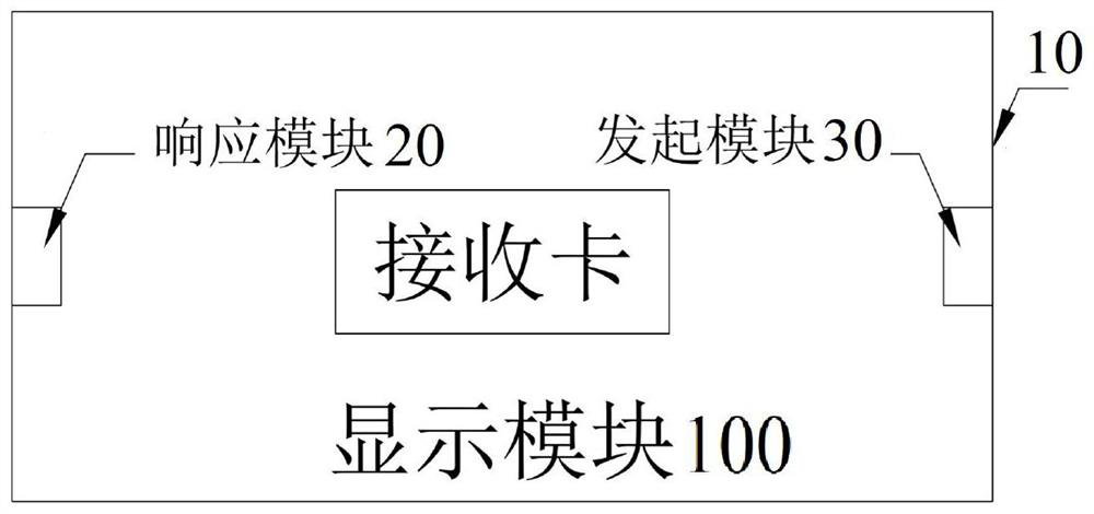
The invention discloses a display device and method for positioning position information of a display device, and the method comprises the steps: selecting one display module, determining the positioning position information of the display module in a lateral / longitudinal direction where the display module is located according to the matching response relationship between an initiating module anda response module between adjacent display modules, generating and feeding zone bit information of the display module back to a control system; determining and selecting adjacent longitudinal / transverse display modules of the display module in the longitudinal / transverse direction according to the cascade connection relationship of the display modules in the longitudinal / transverse direction; andaccording to the matching response relationship between the initiating module and the response module between the adjacent display modules, determining positioning position information of the displaymodules in the transverse / longitudinal direction where the adjacent longitudinal / transverse display modules are located, generating flag bit information of the display modules, and feeding back the flag bit information to the control system. Through the embodiment of the invention, the problem of transverse / longitudinal signal transmission between the display modules can be solved, and the position information of the display device can be automatically displayed.

Description

technical field [0001] The invention relates to the display field, in particular to a display device and a method for positioning position information of the display device. Background technique [0002] In the prior art, the display screen is formed by splicing multiple display modules, and video signals between the modules are transmitted through network cables. With the expansion of display application scenarios, new scenarios such as intelligent detection, intelligent splicing and intelligent control have new requirements for display screens. [0003] The so-called intelligent detection refers to the combination identification technology including software and hardware. Through the information identification of the unit board, the installation position and working status of the display module in the whole screen can be obtained, and then quickly set and controlled. [0004] In the smart screen splicing scenario, the splicing accuracy between display modules can be fed b...

Claims


Application Information

Patent Timeline
Patent Type & Authority Applications(China)
IPC IPC(8): G06F3/14
CPCG06F3/1423
Inventor 王朝朱卫强
Owner UNILUMIN GRP
Learn More