Magnetic particle separation device and nucleic acid or protein separation and purification method using the device

A technology of magnetic particles and separation devices, applied in magnetic separation, stress-stimulated microbial growth methods, solid separation, etc., to achieve the effect of flexible application

Active Publication Date: 2018-12-21
BIONEER
View PDF21 Cites 0 Cited by
  • Summary
  • Abstract
  • Description
  • Claims
  • Application Information

AI Technical Summary

Problems solved by technology

[0005] In the case of the above-mentioned U.S. published patent, in order to combine the receiving part 501 with the separation device 101, inconvenience such as screw connection is required, and in order to eliminate the magnetic field provided to the receiving part 501 side, there is a need to separate the receiving part 501 from the separating device 101 again. the inconvenience

Method used


Image

  • Magnetic particle separation device and nucleic acid or protein separation and purification method using the device
  • Magnetic particle separation device and nucleic acid or protein separation and purification method using the device
  • Magnetic particle separation device and nucleic acid or protein separation and purification method using the device

Examples


no. 1 example

[0038] (First Embodiment) Tube-inserted Magnetic Particle Separator

[0039] First, refer to Figure 1 to Figure 5 The first embodiment will be described in detail.

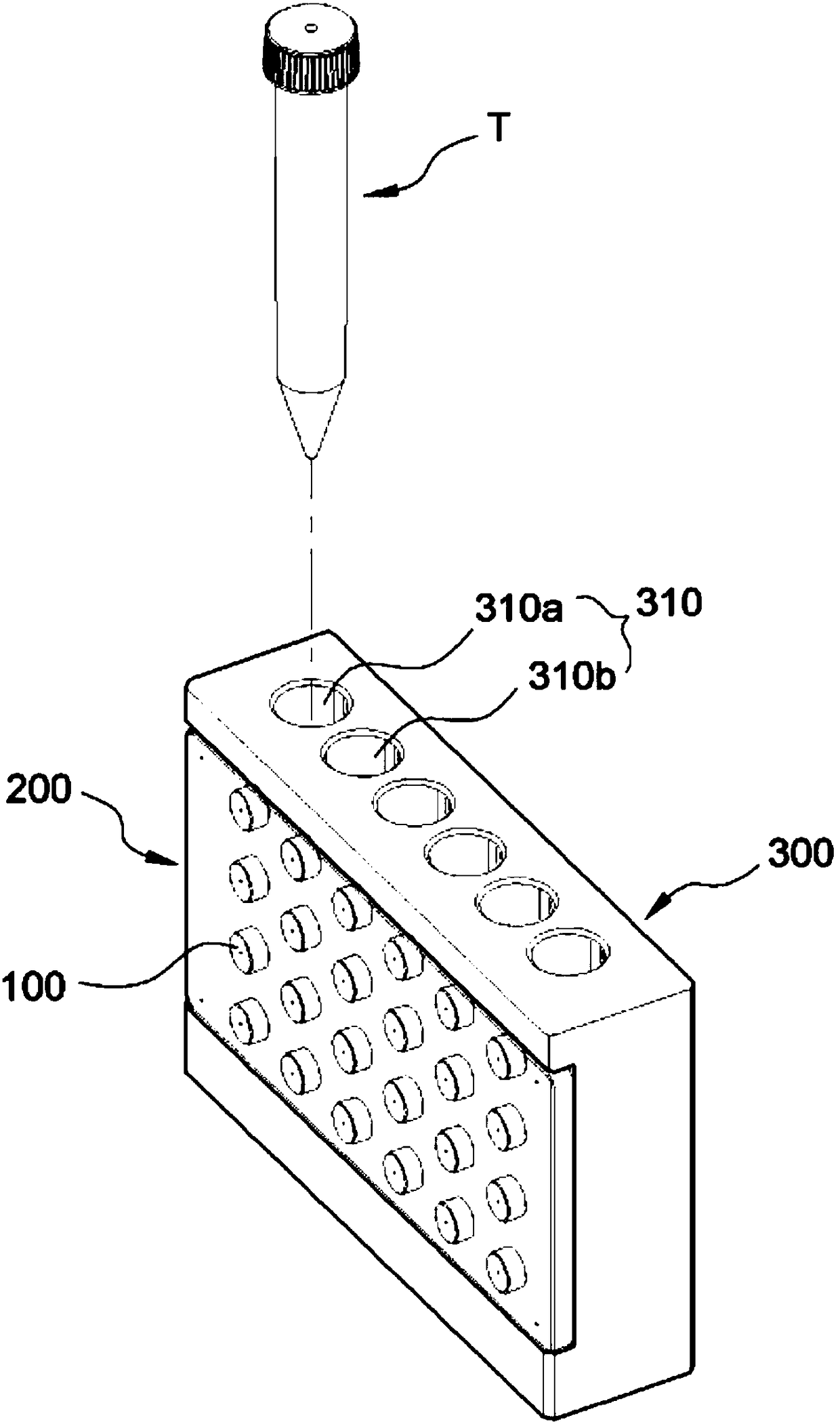
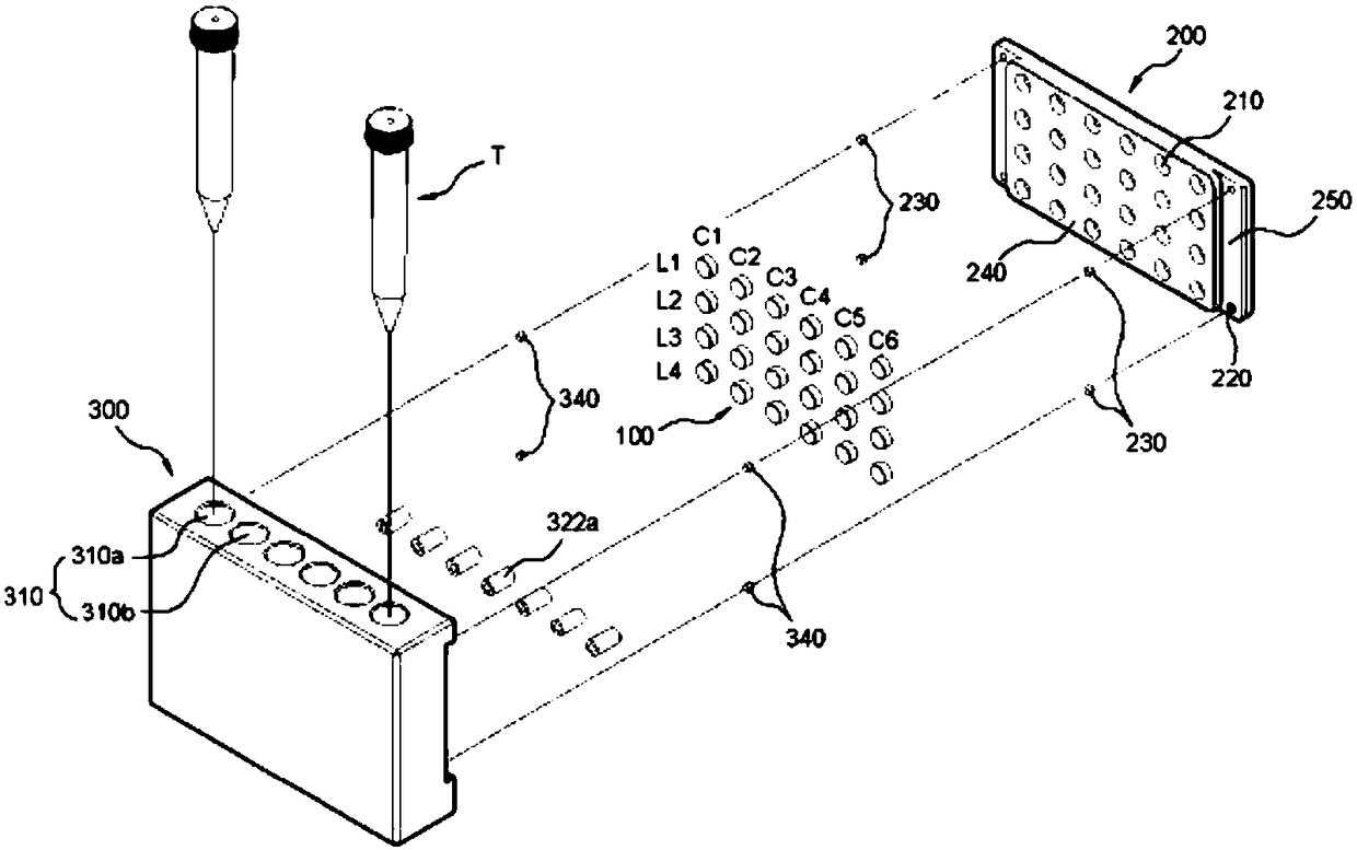
[0040] refer to figure 1 , the present invention has: a main body 300 having a plurality of inflow holes 310 for inserting a substantially cylindrical pipe T; The inductive fixing part 200 roughly forms a plate shape and is combined with one side of the main body 300 .

[0041] refer to figure 2 As a magnetic object, the induction magnet 100 of the present invention preferably has a strength that can form a magnetic field inside the main body 300 or the entire tube T inserted into the main body 300 . exist figure 2 It is shown that the shape of the induction magnet 100 is such as a coin shape and its cross-sectional shape is circular and has a slight thickness, but the cross-sectional shape can be various shapes such as quadrilateral, hexagonal, octagonal, etc., as long as it can be effectively fixed on t...

no. 2 example

[0054] (Second Embodiment) Another Tube Insertion Type Magnetic Particle Separator

[0055] In addition, refer to Figure 6 and Figure 7 Another tube insertion type magnetic particle separation device will be described.

[0056] For the efficiency of the description, the technical features common to the first embodiment above are omitted, so the technical features not described in this embodiment shall be subject to the above embodiment.

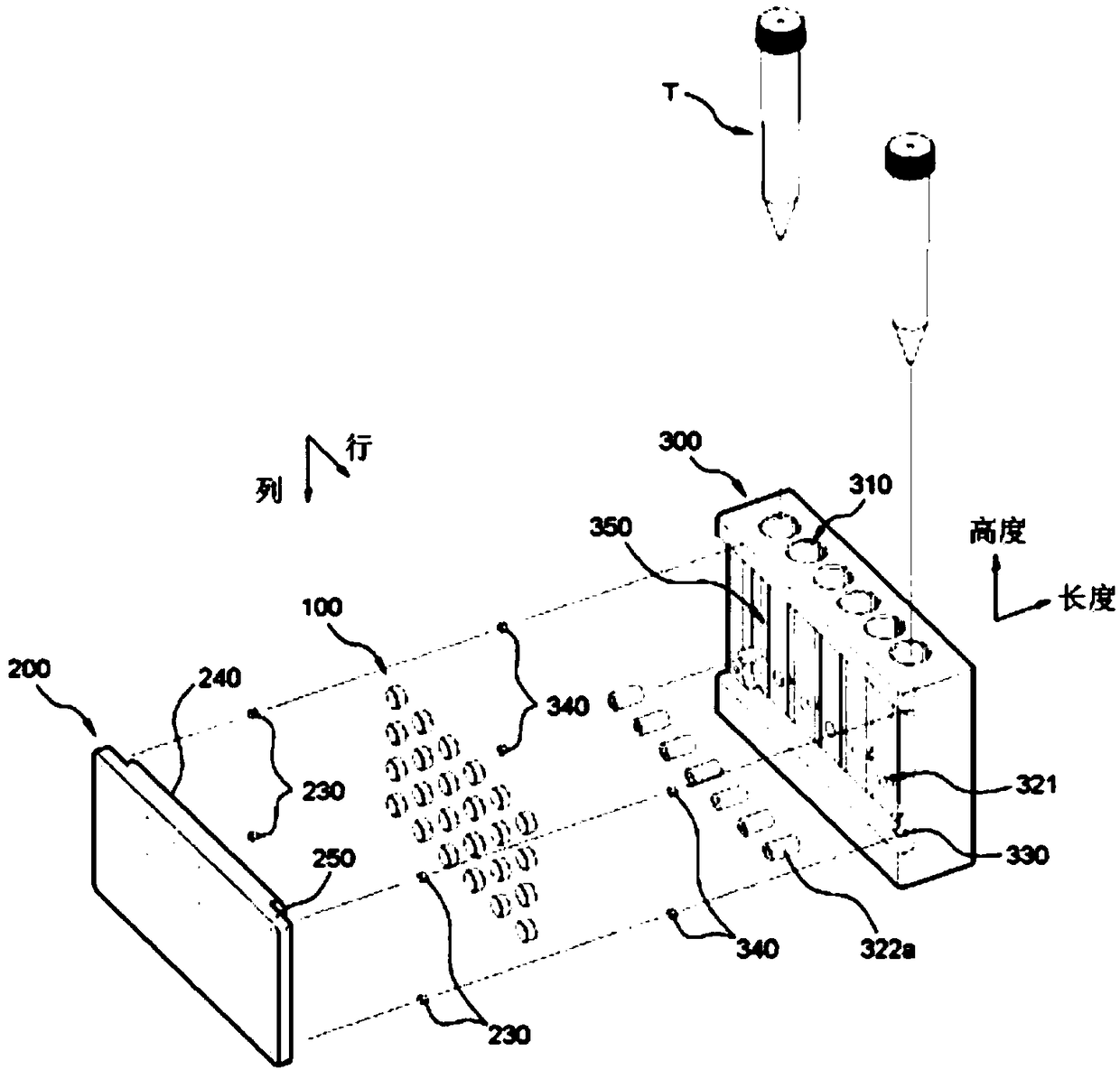
[0057] refer to Figure 6 and Figure 7 , the cross-sectional shape of the inflow hole 310 is roughly "C"-shaped, forming a shape with one side open. From one side of the partition wall 320 to the inner side wall 312 of the main body, a groove portion 360 is formed along the length direction of the main body. The pipe fixing part 322b is inserted along the inner side of the straight groove part 360 formed extending in the width direction. The material of the tube fixing portion 322b is subject to the first embodiment.

[0058] refer ...

no. 3 example

[0062] (Third Embodiment) Third Tube Insertion Type Magnetic Particle Separator

[0063] In addition, refer to Figure 8 Another tube insertion type magnetic particle separation device will be described.

[0064] For the efficiency of the description, the technical features common to the above-mentioned first embodiment and the second embodiment are omitted, so the technical features not described in this embodiment shall refer to the above-mentioned embodiment.

[0065] refer to Figure 8 , the main body 300 exhibits a shape in which a lower surface thereof is opened. In order to prevent the tube T from being damaged when the tube T is inserted into the inflow hole 310, the main body 300 preferably has a height such that the tube T does not touch the bottom surface of the table or the like. Alternatively, referring to the second embodiment, etc., a block P is provided on the outer peripheral surface of the pipe T, so that the pipe T can be prevented from being damaged.

...


PUM


Abstract

The present invention relates to a magnetic particle separation device and a nucleic acid or protein separation and purification method using the device, wherein the magnetic particle separation device comprises: an induction magnet (100); an induction magnet fixing hole ( 210) of the induction magnet fixing part (200); and the main body (300) forming the inflow hole (310) for inserting the pipe (T). Therefore, it is very convenient to apply and cancel the magnetic field on the main body side, and thus can be very effectively applied to the field of separation and purification of nucleic acid or protein.

Description

technical field [0001] The present invention relates to a magnetic particle separation device and a nucleic acid or protein separation and purification method using the device. Background technique [0002] The separation of nucleic acids (DNA and RNA) or proteins from biological samples is the most important step in biochemical research and diagnostic procedures. If the genetic material (nucleic acid) is not isolated from the sample, subsequent steps, namely genetic detection, gene cloning, gene sequencing, gene amplification, and cDNA synthesis, cannot be performed. In order to distinguish DNA or RNA in various cell mixtures, an effective and reproducible separation method is required. Recently, a separation method using magnetic particles is being developed here. The nucleic acid separation method using magnetic particles is a method that uses magnetic particle induction and In the method of using an external magnetic field to separate the genetic material in the test st...

Claims


Application Information

Patent Timeline
Patent Type & Authority Patents(China)
IPC IPC(8): C12M1/42
CPCB03C1/0332B03C2201/18B03C2201/26B01L9/06B01L2200/025B01L2200/0668B01L2400/043B03C1/288B03C1/01C12N15/1013G01N1/405
Inventor 朴翰浯金钟甲
Owner BIONEER
Why Eureka
Try Eureka