Flexible hinge photoelectric composite cable

An optoelectronic composite cable and hinge technology, applied in the direction of insulated cables, communication cables, flat/ribbon cables, etc., can solve the problems of core wire and core wire structure damage, affecting signal transmission ability, etc., to achieve high-efficiency signal transmission, increase Tensile and compressive resistance and bending resistance, the effect of improving the quality of communication

Pending Publication Date: 2020-12-29
BEIJING HENGTONG SIBO COMM TECH CO LTD
View PDF6 Cites 0 Cited by
  • Summary
  • Abstract
  • Description
  • Claims
  • Application Information

AI Technical Summary

Problems solved by technology

[0003] However, photoelectric composite cables are often used in harsh outdoor environments, and it is inevitable that the composite cable will be trampled, squeezed, stretched, impacted, and dragged during construction. Cause damage, and then affect the signal transmission capability, which requires the composite cable to have better compressive strength, tensile strength, and better flexibility
The current conventional photoelectric composite cable cannot meet the above requirements, and a new type of photoelectric composite cable is needed

Method used


Image

  • Flexible hinge photoelectric composite cable
  • Flexible hinge photoelectric composite cable
  • Flexible hinge photoelectric composite cable

Examples


Embodiment Construction

[0020] The present invention will be further described below in conjunction with the embodiments and accompanying drawings.

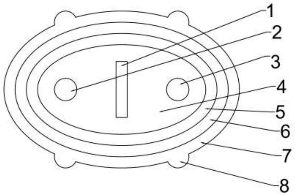
[0021] This embodiment is a flexible hinge photoelectric composite cable and its production method. figure 1 It is a cross-sectional schematic diagram of a flexible hinge photoelectric composite cable. A flexible hinge photoelectric composite cable, including an optical fiber communication unit 2 and an electrical transmission unit 3 arranged parallel to each other, the optical fiber unit 2 is on the left side, the electrical transmission unit 3 is on the right side, and between the optical fiber communication unit 2 and the electrical transmission unit 3 There is a central strengthening member 1 with a longitudinal rectangular cross-section in the center of the center, the left long side of the rectangular cross-section of the central strengthening member 1 is adjacent to the optical fiber communication unit 2, and the right side of the rectangular cro...


PUM

PropertyMeasurementUnit
Bending radiusaaaaaaaaaa
Diameteraaaaaaaaaa

Abstract

The invention belongs to the technical field of communication optical cables, and relates to a flexible hinge photoelectric composite cable, which is characterized in that an optical fiber communication unit and an electric transmission unit are arranged in parallel, the optical fiber communication unit is arranged on the left side, the electric transmission unit is arranged on the right side, a longitudinal central reinforcer with a rectangular cross section is arranged in the center between the optical fiber communication unit and the electric transmission unit, the left long side of the rectangular cross section of the central reinforcer is adjacent to the optical fiber communication unit, the right long side of the rectangular cross section of the central reinforcer is adjacent to theelectric transmission unit, a filler is stranded with the optical fiber communication unit, the electric transmission unit and the central reinforcer to form a cable core with an elliptical cross section, and an inner sheath layer, a hinge layer, an outer sheath layer and a support hand are sequentially coated outside the cable core from inside to outside to form the flexible hinge photoelectric composite cable. According to the invention, the flexible hinge photoelectric composite cable solves the influence of outdoor severe environment on the transmission performance of the photoelectric composite cable, improves the flexibility, interference resistance, water resistance, compression resistance and tension resistance, is stable in signal transmission, is easy to lay and construct, and issuitable for data transmission in the fields of military affairs, finance and the like.

Description

technical field [0001] The invention belongs to the technical field of communication optical cables, in particular to a flexible hinge photoelectric composite cable. Background technique [0002] The photoelectric composite cable is suitable for use as a transmission line in the communication access network system. It is a new type of access method. It integrates optical fiber and power transmission copper wire, and can solve the problems of broadband access, equipment power consumption, and signal transmission. It is often used in Communication remote power supply system and short distance communication system power supply. [0003] However, photoelectric composite cables are often used in harsh outdoor environments, and it is inevitable that the composite cable will be trampled, squeezed, stretched, impacted, and dragged during construction. Cause damage, and then affect the signal transmission capability, which requires the composite cable to have better compressive stre...

Claims


Application Information

Patent Timeline
IPC IPC(8): H01B11/22H01B7/18H01B7/08
CPCH01B11/22H01B7/1875H01B7/184H01B7/182H01B7/1815H01B7/08
Inventor 李为周青宝刘赫韩庆涛冷美潼谢松华王首佳刘显华
Owner BEIJING HENGTONG SIBO COMM TECH CO LTD
Why Eureka
Try Eureka