Method and device for calculating overvoltage stage of direct-current blocking sending-end power grid by considering influence of phase modifier
A technology of DC blocking and calculation methods, which is applied in the direction of AC network voltage adjustment, circuit devices, and AC network circuits, and can solve problems such as multiple overvoltages, transient overvoltages of the AC power grid at the sending end, and off-grid wind turbines at the sending end. , to achieve the effect of accurate calculation
- Summary
- Abstract
- Description
- Claims
- Application Information
AI Technical Summary
Problems solved by technology
Method used
Image

Examples
Embodiment 1
[0044]The first embodiment of the method for calculating the overvoltage phase of the DC blocking transmission end power grid in the present invention considering the influence of the adjustment camera includes the following steps:
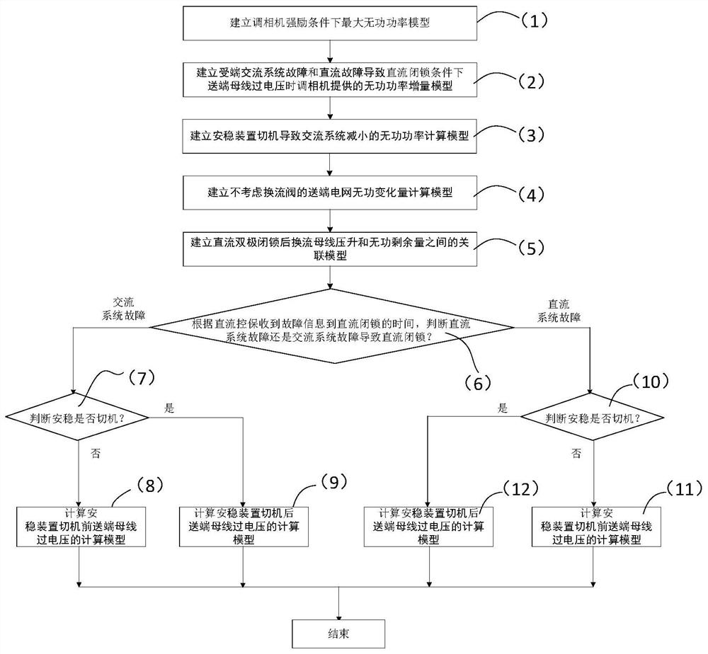
[0045]Step 1. According to the DC control protection information, judge whether the grid fault is the receiving end AC system failure or the DC system failure. If it is the receiving end AC system failure, perform step 2, and if the DC system failure, perform step three; wherein, the DC control protection The information can be the blocking time when the DC control receives the fault information, the DC blocking time caused by the AC system failure at the receiving end is level s, and the DC blocking time caused by the DC system failure is about 100ms.
[0046]Step 2: Determine whether the stability device is switched off according to the switch-off time of the security device, and determine the overvoltage calculation model before and after the device is swi...
Embodiment 2
[0052]Seefigure 1 andfigure 2 The present invention also provides a second embodiment of a method for calculating the overvoltage phase of the DC blocking transmission end power grid considering the influence of the power adjustment, including the following steps:
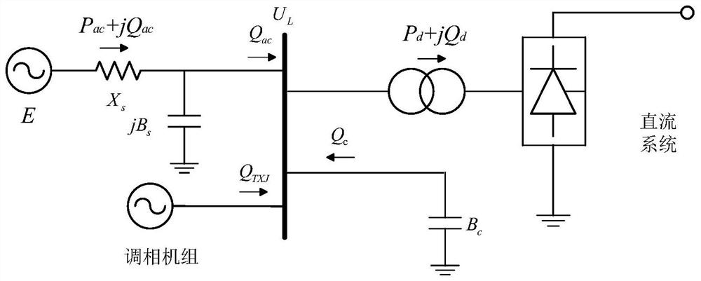
[0053]Step (1): Establish the maximum reactive power value Q that is emitted under the condition of strong excitation of the cameraTXJcx_max model.
[0054]
[0055]Where U is the DC bus voltage, XdTo adjust the stator inductive reactance of the camera, E0 is the terminal potential under normal working conditions, SNTo adjust the rated capacity of the camera, kfm To adjust the camera's strong excitation multiple, KCTo adjust the camera short-circuit ratio.
[0056]Step (2): According to the maximum reactive power model issued under the forced excitation condition of the camera in step (1), and the reactive power value issued by the initial state of the camera, establish the receiving end AC system failure and the DC system failure c...
PUM
 Abstract
Description
Claims
Application Information
 - R&D
- Intellectual Property
- Life Sciences
- Materials
- Tech Scout
- Unparalleled Data Quality
- Higher Quality Content
- 60% Fewer Hallucinations
Browse by: Latest US Patents, China's latest patents, Technical Efficacy Thesaurus, Application Domain, Technology Topic, Popular Technical Reports.
© 2025 PatSnap. All rights reserved.Legal|Privacy policy|Modern Slavery Act Transparency Statement|Sitemap|About US| Contact US: help@patsnap.com