
Motor

A casing and oil circuit technology, applied in the direction of motors, electromechanical devices, electric vehicles, etc., can solve the problems of high heat generation of the motor rotor core, high temperature rise of the magnetic steel, and large space occupation, and improve the cooling effect , compact layout and simple structure

Active Publication Date: 2020-12-29
HYCET TRANSMISSION SYST (JIANGSU) CO LTD BAODING RES & DEV BRANCH
View PDF3 Cites 2 Cited by
  • Summary
  • Abstract
  • Description
  • Claims
  • Application Information

AI Technical Summary

Problems solved by technology

[0003] Water cooling is mainly to use cooling water to dissipate heat inside the motor by forming water channels inside the casing, but since the rotor core of the motor generates a large amount of heat regardless of whether it is a centralized winding or a distributed winding, the cooling effect of the water cooling method is relatively large. Poor, sometimes even cause the temperature rise of the magnetic steel to be too high and bring the risk of demagnetization of the magnetic steel
[0004] Oil cooling is mainly through the design of oil passages inside the casing or the end covers on both sides, and adding a drainage structure above the windings to cool the motor stator. However, the existing oil-cooled motors have complex structures and occupy a large space. Conflicting requirements for small size of automotive motors

Method used


Image

  • Motor
  • Motor
  • Motor

Examples


Embodiment Construction

[0042] It should be noted that, in the case of no conflict, the embodiments of the present invention and the features in the embodiments can be combined with each other.

[0043] The present invention will be described in detail below with reference to the accompanying drawings and examples.

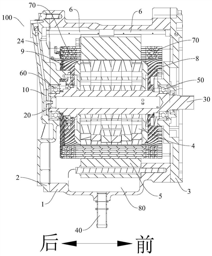
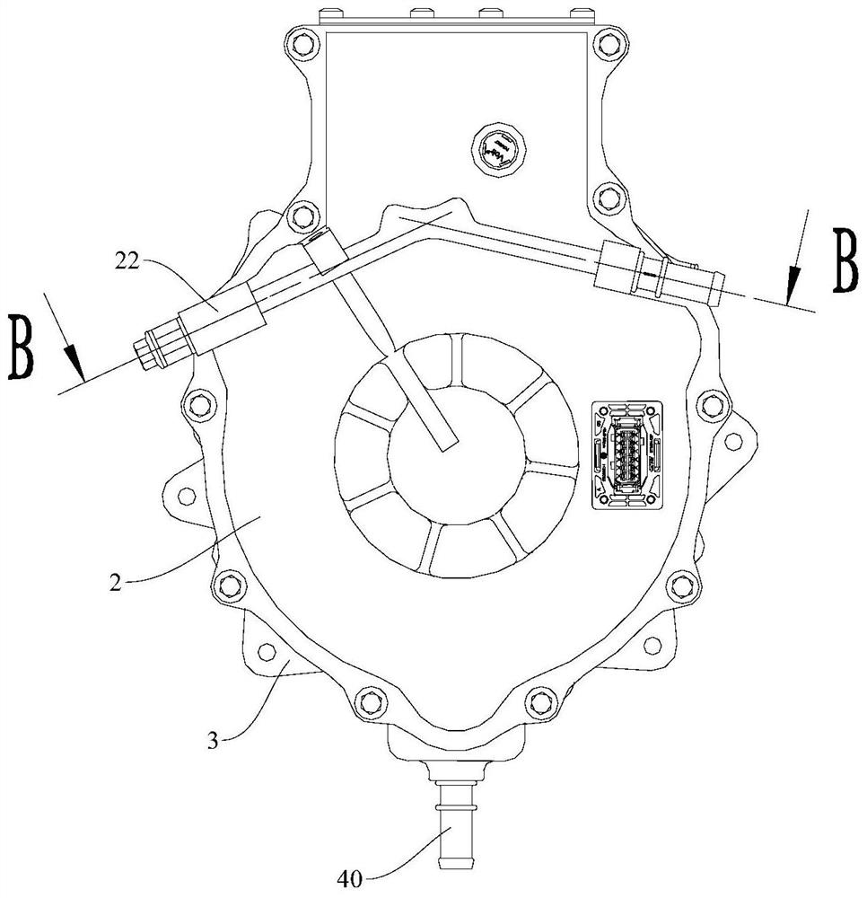
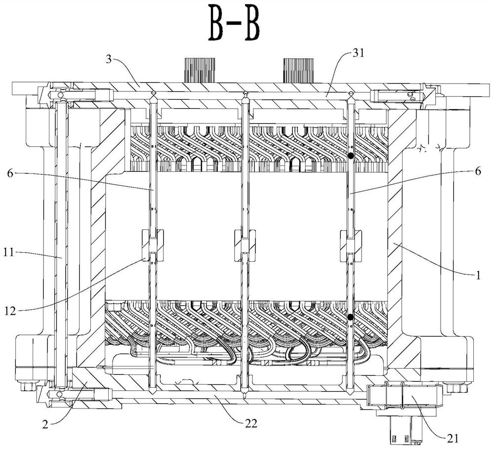
[0044]The motor 100 according to one embodiment of the invention includes: a casing 1 , a rear end cover 2 , a front end cover 3 , a stator and at least one set of fuel injection pipes 6 . Wherein, the rear end cover 2 and the front end cover 3 are installed on the rear end surface and the front end surface of the casing 1 respectively, the rear end cover 2 is provided with an oil inlet pipe 21 and a rear end cover oil passage 22 communicated with the oil inlet pipe 21, the front end The cover 3 is provided with a front cover oil passage 31, and both the front end cover oil passage 31 and the rear end cover oil passage 22 are designed as cross oil passages, and the angle between the two ...


PUM


Abstract

The invention provides a motor. The motor comprises a casing, a rear end cover, a front end cover, a stator and at least one group of oil injection oil pipes, wherein the rear end cover and the frontend cover are respectively arranged on the rear end surface and the front end surface of the casing, the rear end cover is provided with an oil inlet pipe and a rear end cover oil way communicated with the oil inlet pipe, and the front end cover is provided with a front end cover oil way; the rear end cover oil way is communicated with the front end cover oil way through a connecting oil pipe; thestator is arranged in the shell; one of the two oil injection pipes in at least one set of oil injection pipes is installed on the rear end cover and communicated with the rear end cover through an oil way, the other oil injection pipe is installed on the front end cover and communicated with the front end cover through an oil way, and each oil injection pipe is provided with an oil injection hole penetrating through the peripheral wall of the oil injection pipe; the oil injection holes are at least used for cooling a stator core and a winding end part of the stator. According to the motor, through the stator cooling oil way and the rotor cooling oil way, cooling of the motor can be effectively achieved, the cooling effect of the motor is good, and working reliability is high.

Description

technical field [0001] The invention relates to the technical field of motors, in particular to a motor. Background technique [0002] With the increase in the power density of new energy vehicle motors, the requirements for heat dissipation of motors are also getting higher and higher. In the existing new energy vehicle motors, the main cooling methods used are water cooling and oil cooling. [0003] Water cooling is mainly to use cooling water to dissipate heat inside the motor by forming water channels inside the casing, but since the heat generated by the rotor core of the motor is large no matter whether it is a centralized winding or a distributed winding, the cooling effect of the water cooling method is relatively large. Poor, sometimes even cause the temperature rise of the magnetic steel is too high and bring the risk of magnetic steel demagnetization. [0004] Oil cooling is mainly through the design of oil passages inside the casing or the end covers on both si...

Claims


Application Information

Patent Timeline
Patent Type & Authority Applications(China)
IPC IPC(8): H02K5/20H02K1/32H02K9/19
CPCH02K5/20H02K1/32H02K9/19Y02T10/64
Inventor 李义兵魏玉龙邵长志金连多孙厚朝米义鹏吴磊
Owner HYCET TRANSMISSION SYST (JIANGSU) CO LTD BAODING RES & DEV BRANCH
Learn More