Rotor position detection device and positioning and operation control method of switched reluctance motor

A switched reluctance motor and rotor position detection technology, which is applied in motor control, AC motor control, electromechanical devices, etc., can solve the problems that the motor is not in the optimal state, the rotor position cannot be accurately obtained, etc., and achieve accurate calculation and positioning methods Accurate and improve the effect of system operation efficiency

Active Publication Date: 2020-12-29
SHANDONG ACAD OF SCI INST OF AUTOMATION
View PDF4 Cites 1 Cited by
  • Summary
  • Abstract
  • Description
  • Claims
  • Application Information

AI Technical Summary

Problems solved by technology

[0005] However, the inventor believes that the above-mentioned turn-on logic can realize the operation of the motor, but the turn-on and turn-off of each phase of the motor is not an optimal state; The position angle of the rotor is controlled by turning on or off the motor when the rotor ro

Method used


Image

  • Rotor position detection device and positioning and operation control method of switched reluctance motor
  • Rotor position detection device and positioning and operation control method of switched reluctance motor
  • Rotor position detection device and positioning and operation control method of switched reluctance motor

Examples


Embodiment 1

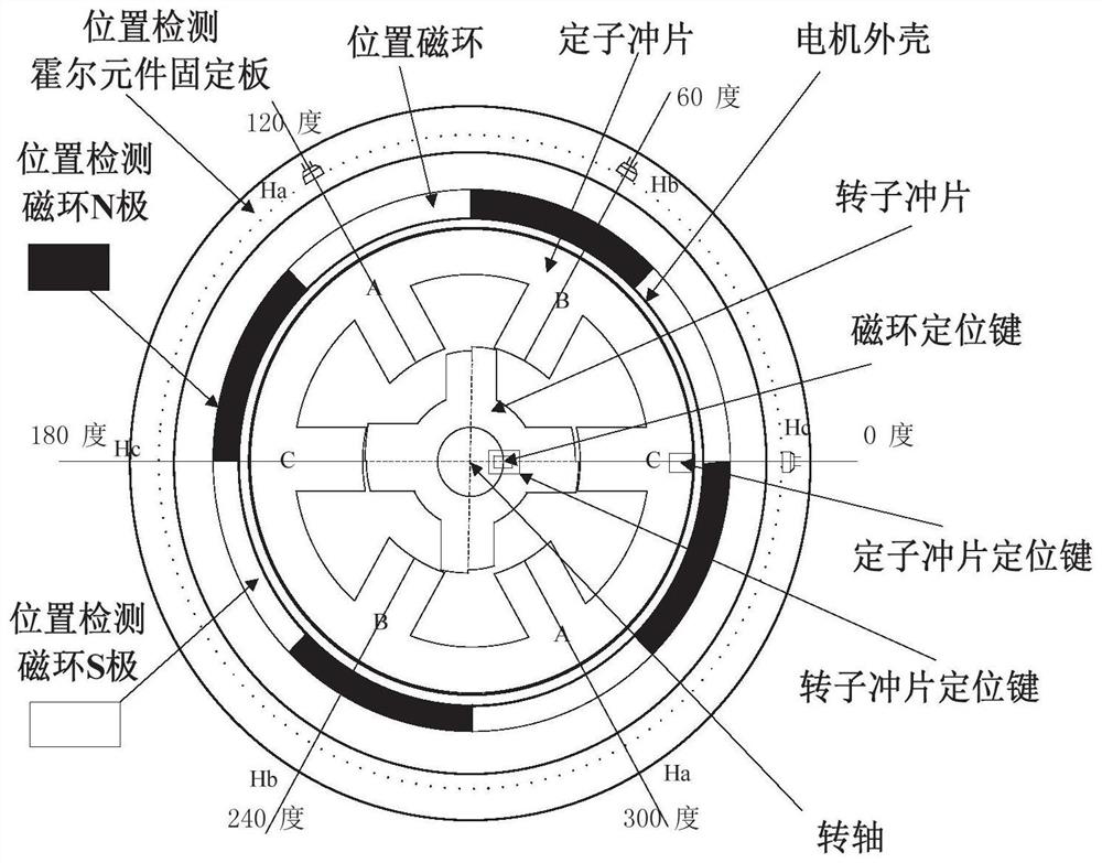
[0035] like figure 1 As shown, this embodiment provides a rotor position detection device for a switched reluctance motor, including: a switched reluctance motor, a magnetic ring positioning key, a rotor punching positioning key, and a stator punching positioning key;

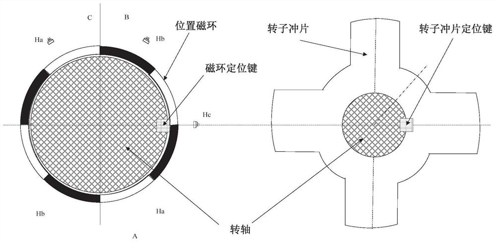
[0036] The position magnetic ring is installed on the rotating shaft of the switched reluctance motor, and the position magnetic ring includes magnetic poles N and magnetic poles arranged alternately, and the magnetic ring positioning key is installed in the alternate position and in the horizontal direction of the axis of the rotating shaft, and the magnetic ring positioning The installation position of the key is the same as that of the positioning key of the rotor punch; the positioning key of the stator punch is installed on the axis of the stator punch of the switched reluctance motor, and a Hall element is installed at the axis of the stator punch;

[0037] The rotor rotation angle is obtained according t...

Embodiment 2

[0052] This embodiment provides a positioning method for a rotor position detection device of a switched reluctance motor. The device uses the device described in Embodiment 1, including:

[0053] S1: Set the horizontal position of the shaft axis where the magnetic ring positioning key and the rotor punching positioning key are located to zero angle; initialize the state of the Hall element, and set the number of current state changes to zero;

[0054] S2: Obtain the pulse signal sequence of the Hall element during the rotation of the position magnetic ring, obtain the state change times of the Hall element, and obtain the first rotation angle according to the state change times of the Hall element;

[0055] S3: Obtain the motor speed according to the time of two adjacent state transitions of the Hall element;

[0056] S4: Obtain the number of motor interruptions and a single angle increment in the state change cycle according to the motor speed;

[0057] S5: Obtain the rotor...

Embodiment 3

[0097] This embodiment provides a method for controlling the turn-on and turn-off angles of the motor during operation based on the rotor position of the switched reluctance motor, including:

[0098] S1: Obtain the interrupt increment value according to the target turn-on angle or target turn-off angle and the single angle increment obtained by the method described in the second aspect;

[0099] S2: judging whether the rotor rotation angle reaches the interrupt increment value, so as to control the turn-on angle or turn-off angle of the switched reluctance motor.

[0100] like Figure 4 As shown, the linear inductance curve of the B-phase winding of the switched reluctance motor is used for illustration. When the state 010->011 transitions, the angle is 0 degrees; when the state 011->001 transitions, the angle is 15 degrees. At this time, the B-phase inductance is in the minimum value state ;State 001->101 transition, the angle is 30 degrees, at this time, the inductance slo...


PUM


Abstract

The invention discloses a rotor position detection device and a positioning and operation control method for a switched reluctance motor, and the method comprises the steps that a position magnetic ring is installed on a rotating shaft of the switched reluctance motor, wherein the position magnetic ring comprises a magnetic pole N and a magnetic pole S which are alternately arranged; and a magnetic ring positioning key is installed at an alternate position and in the horizontal direction of the axis of the rotating shaft, wherein the magnetic ring positioning key and a rotor punching sheet positioning key are installed at the same position; and a stator punching sheet positioning key is installed on the axis of a stator punching sheet of the switched reluctance motor, and a Hall element isinstalled at the axis of the stator punching sheet. A rotor rotation angle is obtained according to the position magnetic ring and a pulse signal column of the Hall element in the rotation process soas to obtain a rotor position. An opening angle or a closing angle is controlled according to the rotor rotation angle and the motor interruption times of the Hall element state conversion period, soas to realize the detection of the rotor position and the control of the motor operation.

Description

technical field [0001] The invention relates to the technical field of motor control, in particular to a rotor position detection device and a positioning and operation control method of a switched reluctance motor. Background technique [0002] The statements in this section merely provide background information related to the present invention and do not necessarily constitute prior art. [0003] In the relationship table between the conduction phase of the motor and the Hall state, the motor is running in a single-phase-two-phase-single-phase alternating power-on mode, and each phase has three states to keep power on and three states to keep power off, that is, the Hall element When HaHbHc(011), phase A remains on, phase B is powered off, and phase C is powered off; when Hall element HaHbHc(001), phase A remains on, phase B starts to be powered on, and phase C is powered off; Hall element When HaHbHc(101), phase A is powered off, phase B starts to stay on, and phase C is...

Claims


Application Information

Patent Timeline
IPC IPC(8): H02K29/08H02K1/18H02K1/28H02K15/00H02P6/16H02P25/086
CPCH02K29/08H02K1/185H02K1/28H02K15/00H02P6/16H02P25/086H02P2203/03
Inventor 周广旭朱孟美杨亭齐威慕永云宋宁冉高佳郭磊
Owner SHANDONG ACAD OF SCI INST OF AUTOMATION
Why Eureka
Try Eureka