Vehicle positioning system for aircraft engine installation and its positioning method

An aircraft engine and positioning system technology, applied in aircraft assembly, aircraft parts, and mechanical devices, etc., can solve the problems of inaccurate positioning, small operating distance, and difficulty in implementation, to ensure efficiency and quality, improve operating distance, and positioning. method accurate effect

Active Publication Date: 2016-12-07
SHENYANG AIRCRAFT CORP
View PDF6 Cites 0 Cited by
  • Summary
  • Abstract
  • Description
  • Claims
  • Application Information

AI Technical Summary

Problems solved by technology

The main problem of visual positioning is: positioning is not accurate, it depends entirely on the operator's experience and reference objects, and usually requires repeated operations and adjustments, so it is time-consuming and laborious, and cannot effectively guarantee the efficiency, time and quality requirements of engine installation
The main problem in the positioning of auxiliary positioning devices is that most of these positioning devices are fixed on the installation vehicle, and the working distance is small, and they can only function when the installation vehicle is close to the final working position. If the positioning is not accurate, the installation vehicle needs to be moved back far distance and then push forward to reposition
After the installation vehicle is far away from the aircraft structure, it can only be positioned visually, so most of the positioning work still depends on vision; in addition, the positioning device on the existing engine installation vehicle needs to be compatible with the aircraft (engine compartment) The positioning reference or the positioning device derived from it are used together. The typical design is to align the two positioning pins on the vehicle with the two reference holes on the engine compartment structure. In fact, it is necessary to accurately control the angle and position deviation at the same time. , it is very difficult to implement

Method used


Image

  • Vehicle positioning system for aircraft engine installation and its positioning method
  • Vehicle positioning system for aircraft engine installation and its positioning method
  • Vehicle positioning system for aircraft engine installation and its positioning method

Examples


Embodiment Construction

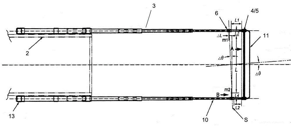
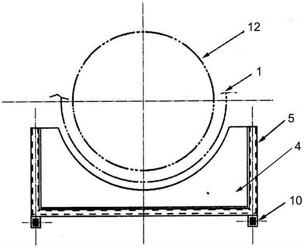
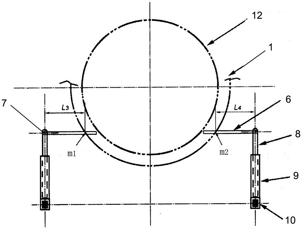
[0020] Such as figure 1 As shown, the aircraft engine is equipped with a vehicle positioning system, which includes two sets of multi-section telescopic arms 3, a clamp 4, a clamp base 5 and a pair of measuring arms 6, wherein the two sets of telescopic arms 3 are placed in parallel and They are respectively installed on the outside of the two longitudinal guide rails 2 at the front end of the installation vehicle. The telescopic support arm 3 adopts a multi-section telescopic structure, and the last support arm at the rear end is fixedly connected with the longitudinal guide rail 2 as a fixed section. The movable section can be stretched or shortened freely, and the first section of the support arm 10 at the front end is engraved with a scale line. The clamping plate 4 and the clamping plate base 5 are installed laterally on the end of the first section support arm 10 at the front end, and a beam handle 11 is connected to the front of the clamping plate base 5 .

[0021] Suc...


PUM


Abstract

The invention provides a positioning system for an aeromotor installing vehicle. The positioning system comprises two multistage telescopic supporting arms, a clamping board, a clamping board bottom seat and a pair of measuring arms; according to the positioning system, the design of the multistage telescopic supporting arms are adopted, so that the operating distance of the positioning system is improved effectively, the positioning function can be played in a long distance, and efficient operation is sustained all the time during the process that the installing vehicle moves to the final operating position, so that the positioning system for the aeromotor installing vehicle is one sustaining positioning system, and the accuracy of the system is improved with the decrease of the distance between the installing vehicle and an engine compartment of the aeromotor. A positional method studied and designed according to the positioning system has the advantages that accurate and efficient measuring and control can be conducted on the angular deviation and the lateral displacement deviation, and the measuring and control over the lateral displacement deviation adopt a combining mode of coarse positioning and fine positioning, so that the positional method is accurate, fast and efficient.

Description

technical field [0001] The invention relates to a positioning system for an aircraft engine installation vehicle and a positioning method thereof, belonging to the technical field of aircraft engine installation. Background technique [0002] The aircraft engine installation vehicle is an important aircraft comprehensive support equipment, which is used for engine installation, disassembly and oil seal, etc., and also has the function of short-term storage and short-distance transfer of the engine. [0003] The weight and size of modern jet engines are large, and the fixed connection on the aircraft is complicated, requiring precise positioning, so the thick waist uses special equipment such as engine installation vehicles. [0004] At present, the jet engine installation vehicle mainly adopts the methods of visual positioning and auxiliary positioning device positioning. The main problem of visual positioning is: positioning is not accurate, it depends entirely on the oper...

Claims


Application Information

Patent Timeline
Patent Type & Authority Patents(China)
IPC IPC(8): B64F5/00G01B5/02G01B5/24B64F5/10
Inventor 赵长辉焦玉坤李波王琦
Owner SHENYANG AIRCRAFT CORP
Why Eureka
Try Eureka