Steel pipe end rounding device

A pipe end and steel pipe technology, which is applied in the field of steel pipe end rounding devices, can solve the problems of steel pipe surface indentation, heavy workload, and low efficiency, and achieve the effects of high work efficiency, round and beautiful appearance, and good flexibility

Pending Publication Date: 2021-01-01
SHANGHAI TIAN YANG STEEL TUBE
View PDF0 Cites 7 Cited by
  • Summary
  • Abstract
  • Description
  • Claims
  • Application Information

AI Technical Summary

Problems solved by technology

[0004] In order to solve the above-mentioned technical problems, the present invention provides a steel pipe end rounding device, through the cooperation of the outer diameter rounding roller and the inner diameter rounding roller, the method of rolling rounding is adopted, which solves the problem that the existing rounding device needs to be carried out. Multiple inspections and multiple times of clamping and fixing the steel pipe to change the position of pressure, the workload is heavy, the efficiency is low, and it will cause the problem of indentation or crease on the surface of the steel pipe

Method used


Image

  • Steel pipe end rounding device
  • Steel pipe end rounding device

Examples


Embodiment

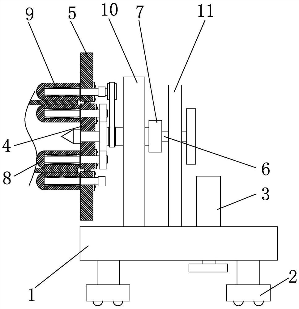
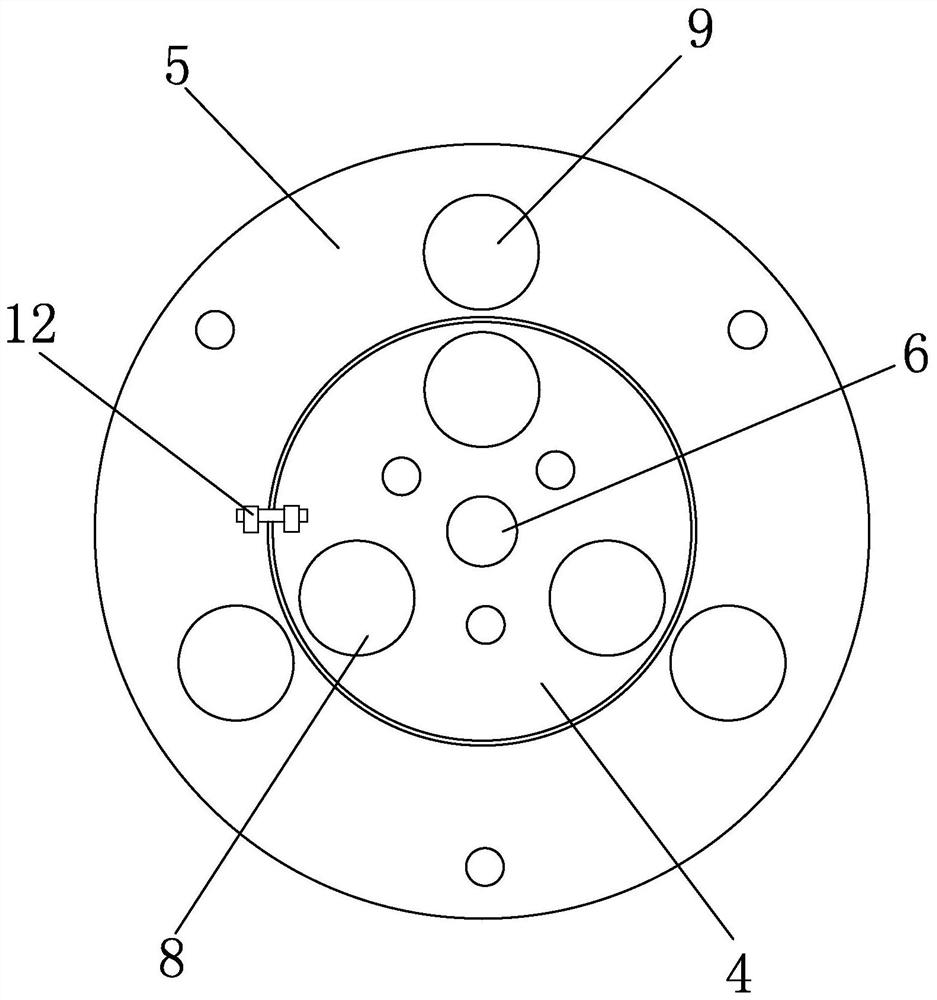
[0029]Combinefigure 1 withfigure 2, The present invention is a rounding device for the end of a steel pipe, which is used for the rounding operation of the end of the steel pipe. The rolling rounding method is adopted, and the steel pipe does not need to be clamped and fixed multiple times, and the rounding operation can be completed at one time. The present invention includes a movable seat 1, a supporting component installed on the movable seat 1, and a round mechanism fixed and movably arranged on the movable seat 1 through the supporting component. Generally, in order to facilitate the movement of the movable seat 1, a T-shaped slider 2 is installed under the movable seat 1, and a ball is provided at the bottom of the T-shaped slider 2. In the present invention, the T-shaped sliding block 2 is installed in the T-shaped chute and moves along the T-shaped chute. The support assembly is mainly used to install and fix the full circle mechanism.

[0030]The full circle mechanism is the ...


PUM


Abstract

The invention relates to the field of pipe machining, and discloses a steel pipe end rounding device. The device comprises a movable base, a supporting assembly and a rounding mechanism, wherein the rounding mechanism comprises an outer rounding assembly and an inner rounding assembly; the inner rounding assembly comprises a main shaft, an inner disc and inner diameter rounding rollers, wherein the inner disc is of a disc-shaped structure, and the main shaft and the inner disc are coaxially arranged and connected; at least one group of inner diameter rounding rollers are arranged on the innerdisc; the outer rounding assembly comprises an outer disc and outer diameter rounding rollers, wherein the outer disc is annular, is concentric with the inner disc, and sleeves the exterior of the inner disc; and at least one group of outer diameter rounding rollers are arranged on the outer disc. According to the steel pipe end rounding device, rolling systems are formed on the inner wall and theouter wall of a steel pipe correspondingly, and meanwhile rolling rounding is conducted at the same time, so that longitudinal creases are effectively prevented from appearing on the surface of a pipe end in the rounding process. The device is high in work efficiency and suitable for mass production of welded steel pipes, the ovality of the pipe end shaped through the device is smaller than or equal to 0.3%, and the rounding effect is good.

Description

Technical field[0001]The invention relates to the field of pipe processing, in particular to a rounding device for the end of a steel pipe.Background technique[0002]The ends of the oil and gas high pressure pipelines are connected by welding. Therefore, there are a large number of welds on high-pressure oil and gas pipelines, and the defects of weld cracks and residual stresses are the main reasons for the failure of high-pressure oil and gas pipelines. Welding cracks often cause high-pressure pipelines to burst and convey medium leakage and other safety hazards. In order to ensure the quality of the weld, the two ends of the steel pipe that need to be welded are rounded in advance, so that the pipe ends during welding are more accurate and convenient.[0003]The traditional rounding device applies pressure radially along the two sides of the pipe end of the oil and gas high-pressure pipeline with the largest pipe diameter, so that the pipe end is plastically deformed. Each time press...

Claims


Application Information

Patent Timeline
Patent Type & Authority Applications(China)
IPC IPC(8): B21D3/05
CPCB21D3/05
Inventor 何建忠
Owner SHANGHAI TIAN YANG STEEL TUBE
Why Eureka
Try Eureka