Forging press with buffering function for machining mechanical parts

A technology for mechanical parts and forging presses, applied in mechanical equipment, metal processing equipment, manufacturing tools, etc., can solve problems such as body damage, and achieve the effect of reducing damage, strong overall linkage, and reducing impact

Inactive Publication Date: 2021-01-01
张国军
View PDF7 Cites 0 Cited by
  • Summary
  • Abstract
  • Description
  • Claims
  • Application Information

AI Technical Summary

Problems solved by technology

[0009] The technical problem to be solved in the present invention is to provide a forging press for processing mechanical parts with a buffer function, the purpose of which is to have a shock-absorbing and buffering effect, and to solve the problem of damage to the machine body caused by vibration and impact

Method used


Image

  • Forging press with buffering function for machining mechanical parts
  • Forging press with buffering function for machining mechanical parts
  • Forging press with buffering function for machining mechanical parts

Examples


Embodiment 1

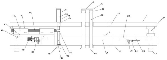
[0048] Such as Figure 1-Figure 9 As shown, the present invention provides a forging press for processing mechanical parts with a buffer function, including a frame mechanism 1, and the frame mechanism 1 includes a workbench 11 and a bottom plate 15, and between the workbench 11 and the bottom plate 15 The track mechanism 2, the track mechanism 2 includes a semi-circular rail plate 21, the semi-circular rail plate 21 is fixedly welded on the upper side panel of the base plate 15, and the upper side panel of the semi-circular rail plate 21 is excavated with a motor track groove 23, and the motor track groove 23 one side of the corresponding semi-annular rail plate 21 is excavated with an embedded rack 24, and the embedded rack 24 is away from the motor track groove 23. The corresponding semi-annular rail plate 21 is excavated with an annular slide rail 25 on the side of the motor track. The inside of the groove 23, the embedded rack 24 and the annular slide rail 25 is provided ...

Embodiment 2

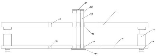
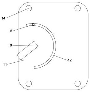
[0053] Such as Figure 1-2 As shown, on the basis of Embodiment 1, the present invention provides a technical solution: a No. 1 pressing bar track groove 12 is drilled through the worktable 11 corresponding to the pressing bar mechanism 5, and the No. 1 pressing bar track groove 12 directly below corresponds to No. 2 push rod track groove 16 is drilled through the bottom plate 15 of the bottom plate, and a No. 1 ejector bushing 13 is drilled through the worktable 11 corresponding to the center of the semi-circular rail 21, and a bottom plate corresponding to No. 1 ejector bush 13 is drilled. No. 2 ejector bushing 17 is drilled through 15, and the four corners of the lower side panel of the worktable 11 and the four corners of the upper side panel of the bottom plate 15 are fixed and welded vertically through the middle liner 14 one by one. The four corners of the side panels are fixedly welded with bottom pads 18 , the bottom plate 15 is at the orthographic projection of the w...

Embodiment 3

[0057] Such as figure 1 , 4 As shown in and 5, on the basis of Embodiment 1, the present invention provides a technical solution: Preferably, the semi-annular rail plate 21 corresponding to the motor track groove 23 and the embedded rack 24 has a fitting groove inside , the depth of the annular slide rail 25 is greater than the depth of the fitting groove, the orientation of the annular slide rail 25 and the orientation of the embedded rack rail 24 are perpendicular to each other, and the embedded rack rail 24 faces directly upward, and the inner and outer sides of the motor track groove 23 Limiting track grooves 22 are drilled on the upper side panels of the corresponding semi-circular rail plates 21 .

[0058] In this embodiment, the notch on the semi-circular track plate 21 and the embedded rack 24 enable the track mechanism 2 and the power mechanism 3 to interact with each other, and play the role of an intermediate linkage component. This design makes the frame mechanism...


PUM


Abstract

The invention discloses a forging press with a buffer function for machining mechanical parts, and belongs to the technical field of mechanical equipment. The forging press comprises a frame body mechanism, the frame body mechanism comprises a worktable plate and a bottom plate, a rail mechanism is arranged between the worktable plate and the bottom plate, the rail mechanism comprises a semi-annular rail plate, the semi-annular rail plate is fixedly welded to an upper side panel of the bottom plate, a motor rail groove is dug in the upper side panel of the semi-annular rail plate, and an embedded toothed rail is dug in the position, corresponding to one side of the motor rail groove, of the semi-annular rail plate. The design that a U-shaped connecting base and the semi-annular rail plateare connected only through meshing between the embedded toothed rail and a gear enables the vibration conduction performance between the U-shaped connecting base and the semi-annular rail plate is very poor, due to the design, vibration and impact force from a pressing rod mechanism and a limiting mechanism can be dispersed, and the damage to a whole machine body is reduced.

Description

technical field [0001] The invention relates to a forging press, and relates to the technical field of mechanical equipment, in particular to a forging press with a buffer function for processing mechanical parts. Background technique [0002] Forging presses include plate rolling machines, shearing machines, punches, presses, hydraulic presses, hydraulic presses, bending machines, etc. Among them, bending machines can be divided into straight plate bending machines, straight tube bending machines and straight bar bending machines according to the processing parts. bender and more. [0003] There are following problems at prior art: [0004] 1. In the prior art, the structure of the straight rod type bending machine is too rigid, resulting in the problem that most of the workpieces are in rigid contact during the process of placing and processing, and there is no buffer protection structure; [0005] 2. In the existing technology, for some processing processes, there will ...

Claims


Application Information

Patent Timeline
Patent Type & Authority Applications(China)
IPC IPC(8): B21D7/06B21D55/00B21D43/00F16F15/023
CPCB21D7/06B21D55/00B21D43/003F16F15/023F16F2222/12
Inventor 张国军洪美根
Owner 张国军
Why Eureka
Try Eureka