Efficient copper dissolving tank

A high-efficiency technology for dissolving copper tanks, applied in the direction of cells, electrolytic processes, electrolytic components, etc., can solve the problems of low copper dissolving speed, large spray dead zone area, large heat loss, etc., to improve reaction speed and heat release, dissolve The effect of improving the uniformity of copper and reducing the cost of dissolving copper

Inactive Publication Date: 2021-01-01
洪田科技有限公司
View PDF0 Cites 7 Cited by
  • Summary
  • Abstract
  • Description
  • Claims
  • Application Information

AI Technical Summary

Problems solved by technology

Traditional copper melting equipment mainly adopts reverse ventilation spraying process and immersion copper melting process, and the corresponding supporting equipment is a low-temperature spraying copper melting tank. The speed is low, because the flow speed between the copper sulfate liquid / oxygen and the copper material is small, the contact is insufficient, and the heat loss is large, so it is necessary to use large-scale process equipment to increase the output, because the heat generated is not enough to make the temperature in the tank reach the best. The copper sulfate solution needs to be heated by heat exchange equipment, which increases the cost of copper dissolution

Method used


Image

  • Efficient copper dissolving tank
  • Efficient copper dissolving tank
  • Efficient copper dissolving tank

Examples


Embodiment Construction

[0033] In order to make the object, technical solution and advantages of the present invention clearer, the present invention will be further described in detail below with reference to the accompanying drawings and embodiments. However, it should be understood that the specific embodiments described here are only used to explain the present invention, and are not intended to limit the scope of the present invention.

[0034] Unless otherwise defined, all technical terms and scientific terms used herein have the same meaning as commonly understood by those skilled in the technical field of the present invention, and the terms used in the description of the present invention herein are only to describe specific implementations The purpose of the example is not intended to limit the present invention.

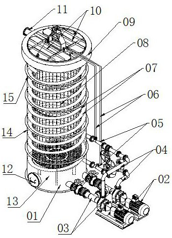
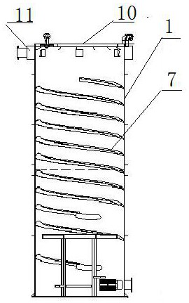
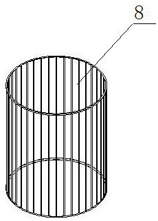
[0035] Such as figure 1 , figure 2 with image 3 As shown, a high-efficiency copper-dissolving tank includes a copper-dissolving tank body 1, and the copper-dissolving tank b...


PUM


Abstract

The invention discloses an efficient copper dissolving tank. The tank comprises a copper dissolving tank body, and the copper dissolving tank body comprises a tank top, a tank cover located on the tank top and liquid feeding systems connected with an external pipeline of the copper dissolving tank body; the liquid feeding systems involve acid-resistant circulating pumps, liquid inlet pipelines, liquid outlet pipelines, liquid oxygen jet mixers and gas inlet pipelines; a copper dissolving device is arranged in the copper dissolving tank body; and the copper dissolving device comprises multi-layer vortex flow channels, a grid cylinder, a suction opening, a manhole device, a bottom liquid discharging hole, a middle liquid outlet hole and an upper liquid supplementing hole. According to the tank, liquid inlets of the acid-resistant circulating pumps are connected with the lower portion of the copper dissolving tank body, liquid outlets of the acid-resistant circulating pumps are connectedwith the liquid oxygen jet mixers, and oxygen-enriched air and copper sulfate liquid are fully mixed through the liquid oxygen jet mixers to form foam flow; and then vortex flow is generated in the tank body through the multi-layer vortex flow channels in the inner wall of the tank body, and huge rotation in the tank body is formed to scour copper materials in the tank, so that the contact area and time are greatly improved, and the copper dissolving speed and efficiency are greatly improved.

Description

technical field [0001] The invention relates to the technical field of high-efficiency copper-dissolving equipment, in particular to a high-efficiency copper-dissolving tank. Background technique [0002] In the production process of electrolytic copper foil, the copper dissolution process is to dissolve solid copper material into copper ions. Copper dissolution is an important part of copper foil production. The efficiency of copper dissolution directly affects the output and cost of copper foil. Traditional copper melting equipment mainly adopts reverse ventilation spraying process and immersion copper melting process, and the corresponding supporting equipment is a low-temperature spraying copper melting tank. The speed is low, because the flow speed between the copper sulfate liquid / oxygen and the copper material is small, the contact is insufficient, and the heat loss is large, so it is necessary to use large-scale process equipment to increase the output, because the h...

Claims


Application Information

Patent Timeline
Patent Type & Authority Applications(China)
IPC IPC(8): C25D21/14C25D21/02
CPCC25D21/02C25D21/14
Inventor 云光义李海涛丁刚东
Owner 洪田科技有限公司
Why Eureka
Try Eureka