The connection structure and connection method of the parts at the thin plate of the spray cooling dust collector

A connection structure, dust collector technology, applied in the direction of thin plate connection, connecting member, threaded fastener, etc., can solve the problems of mechanical properties and sealing, displacement of the center position of nuts and holes, large area deformation of plates, etc. The installation process is fast and convenient, the overall structure is not deformed, and the workload of welding is reduced.

Active Publication Date: 2022-02-18
HUANGSHAN TIANZHIDU ENVIRONMENTAL SCI & TECH DEV CO LTD
View PDF6 Cites 0 Cited by
  • Summary
  • Abstract
  • Description
  • Claims
  • Application Information

AI Technical Summary

Problems solved by technology

[0002] At present, the combination of spray cooling and dust removal is used for the treatment of diesel engine exhaust, which requires a large number of welding nuts to fix small parts. Because the overall plate is relatively thin, a large area of ​​serious deformation is caused during the welding process; The shift of the center position will bring great difficulties to the subsequent assembly and also bring inconvenience to the later maintenance.
[0003] In addition, during the use of the dust collector, due to the pressure requirement, it is necessary to ensure the absolute sealing of the joints of the components. If ordinary screws and nuts are used to install the components on the thinner plate of the current dust collector, it will cause problems in mechanical properties and sealing. waiting to be solved

Method used


Image

  • The connection structure and connection method of the parts at the thin plate of the spray cooling dust collector
  • The connection structure and connection method of the parts at the thin plate of the spray cooling dust collector
  • The connection structure and connection method of the parts at the thin plate of the spray cooling dust collector

Examples


Embodiment Construction

[0041] Next, the technical solutions in the embodiments of the present invention will be described in connection with the drawings of the embodiments of the present invention, and it is understood that the described embodiments are merely the embodiments of the present invention, not all of the embodiments.

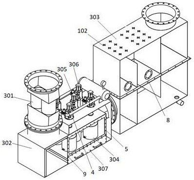
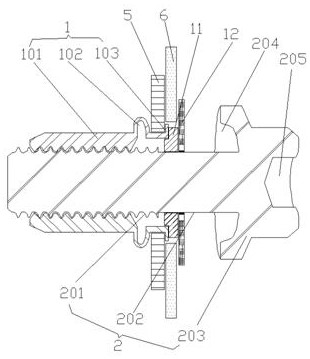
[0042] Refer Figure 1-7 , Cooling the sheet at a connecting structure A spray filter member, comprising a blind rivet nut 2 and screw rivet, particularly spray cooling means dust collector catalytic converters 301, pulse regeneration and carbon black particulate trap housing 302 horizontal cooling spray housing 303 in one of the housing structure, there is provided a pulse regeneration DPF particulate trap soot particles trapped within the body 304 housing 302, DPF particulate trap tank 304 is provided with an outlet to the top lift valve 305 and backflush valve 306, the DPF particulate trap dust tank 304 is provided with a drawer bottom outlet 307, a bottom 305 and backflush...


PUM


Abstract

The invention discloses a connection structure of parts at the thin plate of a spray cooling dust collector, which includes blind rivet nuts and blind screws. The parts at the thin plate and the thin plate at the connection are provided with matching regular hexagonal through holes and perfect circular through holes; the blind rivet nut includes an internal thread section, a bending part and a flat flange; the blind rivet screw includes an external thread section and a smooth cylindrical section And the nut, the smooth cylindrical section is sleeved with a boss ring and a sealing ring; the top surface of the sprinkler mounting seat is provided with a hexagonal groove and a sealing rubber layer, the bottom of the hexagonal groove is provided with a threaded groove, and the top of the sprinkler mounting seat is provided with a hexagonal stainless steel sheet; The invention also provides a corresponding connection method. The present invention simplifies the installation of all parts on the thin plates into the process of installing and fastening two thin plates with regular hexagonal through holes and with perfect circular through holes through blind rivet nuts and blind rivet screws, which improves the installation efficiency and the installation structure Beautiful and good sealing.

Description

Technical field [0001] The present invention relates to the field of dust collector fitting mounting techniques, and more particularly to a connection structure and a connection method of a spray cooling precipitator sheet. Background technique [0002] At present, the treatment of diesel exhaust gas uses spray cooling and dust removal combination, it is necessary to fix a small member for a large number of soldering nuts. Since the entire sheet is relatively thin in the welding process, the large area is severely deformed; and the nut and holes are used in the nut and the hole The central location is shifted, and it has brought great difficulties on the assembly of the following, and it will bring inconvenience to the later maintenance. [0003] In addition, during use of the dust collector, since the pressure needs to ensure the absolute sealing of each component connection, if a common screw nut is used to mount each component thinner sheet material, the mechanical properties ...

Claims


Application Information

Patent Timeline
Patent Type & Authority Patents(China)
IPC IPC(8): F16B5/02F16B5/04F16B19/10F01N3/04F01N13/18
CPCF16B5/04F16B5/02F16B19/1072F01N3/04F01N13/1855
Inventor 王健江嗣中王辉占越洪鸣洪源继王鹏
Owner HUANGSHAN TIANZHIDU ENVIRONMENTAL SCI & TECH DEV CO LTD
Why Eureka
Try Eureka