
Hydraulic torque converter lock-up clutch sliding friction loss compensation control device and control method

A technology of torque converter and lock-up clutch, applied in transmission, transmission control, fluid transmission, etc., can solve the problem that the friction surface affects the friction material and friction performance of the lock-up clutch, and reduces the service life and reliability of the lock-up clutch. The temperature rise of parts and other problems, to achieve the effect of simple judgment criteria, fast switching, and reducing friction and wear

Active Publication Date: 2021-11-09
XIANGTAN UNIV
View PDF4 Cites 0 Cited by
  • Summary
  • Abstract
  • Description
  • Claims
  • Application Information

AI Technical Summary

Problems solved by technology

However, the lock-up clutch is not completed instantaneously from the disengagement condition to the engagement condition, or from the engagement condition to the disengagement condition, and there is a slipping process
However, the existing hydraulic torque converter device with a lock-up clutch does not fully consider the abrasion of the lock-up clutch during the slipping process, especially when the driving conditions are complicated, resulting in an increase in the number of lock-up and unlocking of the lock-up clutch, and the lock-up clutch is in a slipping condition. The time will also become longer, and eventually the friction pair of the lock-up clutch will produce a large amount of sliding work, and the sliding work has an important impact on the temperature change of the lock-up clutch. When the sliding work is too large, it will often cause the temperature of the parts to rise. High, while the temperature of the friction surface is too high will affect the friction material and friction performance of the lock-up clutch, thereby reducing the service life and reliability of the lock-up clutch

Method used


Image

  • Hydraulic torque converter lock-up clutch sliding friction loss compensation control device and control method
  • Hydraulic torque converter lock-up clutch sliding friction loss compensation control device and control method
  • Hydraulic torque converter lock-up clutch sliding friction loss compensation control device and control method

Examples


Embodiment Construction

[0036] The present invention will be further described below in conjunction with the accompanying drawings.

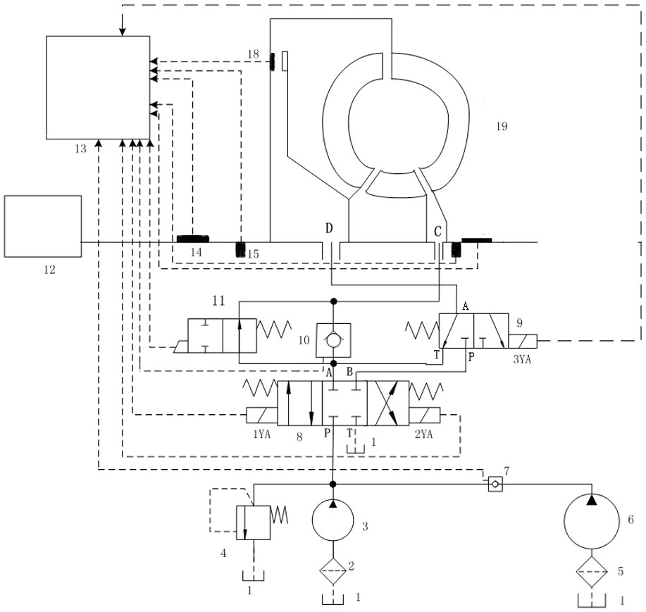
[0037] Such as figure 1 As shown, the hydraulic torque converter lock-up clutch sliding friction loss compensation control device of the present invention includes a hydraulic torque converter 19, a hydraulic device and an electronic control unit 13; the input shaft and the output shaft of the hydraulic torque converter 19 are both A torque sensor 14 and a rotational speed sensor 15 are provided, and a pressure sensor 18 is provided between the lock-up clutch and the housing of the hydraulic torque converter. The input shaft of the torque converter 19 is connected to the engine 12 .

[0038] The hydraulic device includes a fuel tank 1, a small oil pump 3, a large oil pump 6, an overflow valve 4, a three-position four-way reversing valve 8, a stroke valve 11, a one-way valve I7, a one-way valve II10 and a solenoid valve 9; The inlets of the large oil pump 6 and the sm...


PUM


Abstract

The invention discloses a hydraulic torque converter lock-up clutch sliding friction loss compensation control device and control method. The device includes a hydraulic torque converter, a hydraulic device and an electronic control unit; the input shaft and the output shaft of the hydraulic torque converter are Both are equipped with torque sensors and speed sensors, and a pressure sensor is installed between the lock-up clutch and the hydraulic torque converter housing; the hydraulic device includes a fuel tank, a small oil pump, a large oil pump, an overflow valve, and a three-position four-way reversing valve , stroke valve, one-way valve and solenoid valve; torque sensor, speed sensor, pressure sensor, three-position four-way reversing valve, stroke valve, one-way valve II and solenoid valve are respectively connected with the electronic control unit. The invention has simple structure and high control precision, and can realize rapid switching of the locking and unlocking working conditions of the locking clutch of the hydraulic torque converter; shortens the time when the locking clutch is in the slipping working condition, and reduces the sliding friction loss of the locking clutch.

Description

technical field [0001] The invention belongs to the technical field of clutch control, and in particular relates to a hydraulic torque converter lock-up clutch sliding friction loss compensation control device and control method. Background technique [0002] The lock-up slip control technology of the hydraulic torque converter refers to the installation of a controllable clutch between the turbine and the pump wheel of the hydraulic torque converter, which can control the lock-up clutch to connect the turbine and the pump wheel when the car is driving to the set working condition. The pump wheel lock is integrated, so that the hydraulic torque converter changes from hydraulic transmission to rigid body transmission. The application of locking control technology greatly improves the transmission efficiency of the car. However, the lock-up clutch is not completed instantaneously from the disengagement mode to the combination mode, or from the combination mode to the disengage...

Claims


Application Information

Patent Timeline
Patent Type & Authority Patents(China)
IPC IPC(8): F16H61/14
CPCF16H61/143F16H2061/145
Inventor 刘金刚郑剑云傅兵赵又红戴诗雨
Owner XIANGTAN UNIV
Learn More