
Train simulation system and platform

A technology of simulation system and simulation platform, which is applied in the field of train simulation system and platform, can solve problems such as limited input and output ports of single-chip microcomputer, failure to meet the safety level of railway signal system, and reduce real-time performance of the system, so as to ensure real-time performance and reliability, Improve the effect of data acquisition ability and control output ability

Inactive Publication Date: 2021-01-01
通号城市轨道交通技术有限公司
View PDF5 Cites 1 Cited by
  • Summary
  • Abstract
  • Description
  • Claims
  • Application Information

AI Technical Summary

Problems solved by technology

In order to meet the requirements of safety, it is necessary to collect and process the data in the railway signaling system in real time, and the operating system needs to respond within a specified time, while the Window operating system and Linux operating system commonly used in the train simulation system of the prior art The system is a non-real-time operating system, which cannot meet the safety level of the railway signaling system
At the same time, the railway signal system needs to collect a large amount of data, and the collection and output of the control system are large. At present, the train simulation system mostly uses an embedded control system. The input and output ports of the single-chip microcomputer of the embedded system are limited, and a single single-chip microcomputer cannot meet the requirements of the railway signal system. The collection and output of all data in the system, and the use of two or more single-chip microcomputers for data collection and output increases the complexity of the system, and the operating system controls multiple single-chip microcomputers at the same time, which will reduce the real-time performance of the system

Method used


Image

  • Train simulation system and platform
  • Train simulation system and platform
  • Train simulation system and platform

Examples


Embodiment Construction

[0028] In order to make the purpose, technical solutions and advantages of the embodiments of the present invention clearer, the technical solutions in the embodiments of the present invention will be clearly and completely described below in conjunction with the drawings in the embodiments of the present invention. Obviously, the described embodiments It is a part of embodiments of the present invention, but not all embodiments. Based on the embodiments of the present invention, all other embodiments obtained by persons of ordinary skill in the art without creative efforts fall within the protection scope of the present invention.

[0029] The Window operating system and Linux operating system commonly used in the train simulation system of the prior art are non-real-time operating systems, which cannot meet the safety level of the railway signaling system, and the train simulation system of the prior art mostly uses an embedded control system, and the general train needs The...


PUM


Abstract

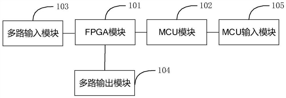
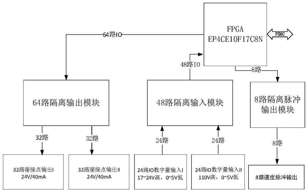
The embodiment of the invention provides a train simulation system and platform. The system comprises an FPGA module, an MCU module, a multi-path input module, a multi-path output module and an MCU input module, wherein the output end of the FPGA module is connected with the input end of the MCU module; the MCU module adopts a real-time operating system; the output end of the multi-path input module is connected with the input end of the FPGA module, and the input end of the multi-path output module is connected with the output end of the FPGA module; and the output end of the MCU input moduleis connected with the input end of the MCU module. The MCU module adopts the real-time operating system to quickly and efficiently process data, so that the real-time performance and the reliabilityof the system are better guaranteed; the FPGA module is used for expanding the ports of a single-chip microcomputer, so that the problem of insufficient ports of the single-chip microcomputer is solved; the FPGA module only performs port expansion, and data processing is completed in the MCU module, so that the stability and the processing efficiency of the system are improved.

Description

technical field [0001] The invention relates to the technical field of rail transit, in particular to a train simulation system and platform. Background technique [0002] In the railway signal system, the requirements for safety, availability and real-time performance are relatively high. In order to meet the requirements of safety, it is necessary to collect and process the data in the railway signaling system in real time, and the operating system needs to respond within a specified time, while the Window operating system and Linux operating system commonly used in the train simulation system of the prior art The system is a non-real-time operating system, which cannot meet the safety level of the railway signaling system. At the same time, the railway signal system needs to collect a large amount of data, and the collection and output of the control system are large. At present, the train simulation system mostly uses an embedded control system. The input and output por...

Claims


Application Information

Patent Timeline
IPC IPC(8): G05B19/042
CPCG05B19/0423G05B2219/25257
Inventor 朱波李少鹏王静田元曾重阳刘龙
Owner 通号城市轨道交通技术有限公司
Learn More