Transformer
A technology for transformers and casings, applied in the field of transformers, can solve problems such as transformer damage and transformer failure to work normally, and achieve the effects of extending service life, preventing rollover and avoiding damage.
- Summary
- Abstract
- Description
- Claims
- Application Information
AI Technical Summary
Problems solved by technology
Method used
Image
Examples
Embodiment 1
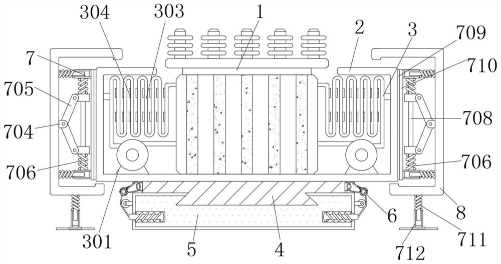
[0034] A transformer, including a transformer 1 and a casing 2, the bottom of the transformer 1 is fixedly connected with the casing 2, the model of the transformer 1 is SCB11, and the outside of the casing 2 is provided with a buffer device 7;
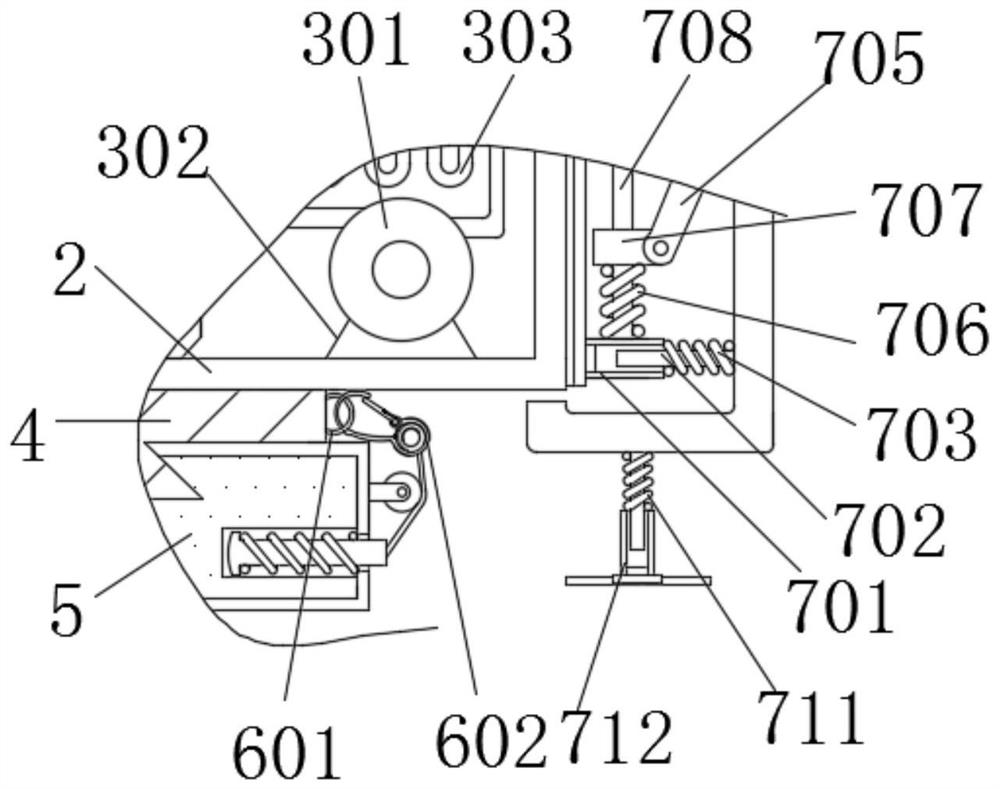
[0035] The buffer device 7 comprises a first sleeve 701, a cross bar 702, a second spring 703, a block 704, a long plate 705, a third spring 706, a slide block 707, a slide bar 708, a first slide track 709, a slide plate 710, a Four springs 711, a second sleeve 712, a vertical bar 713, a sliding block 714 and a second sliding track 715;
[0036]The first sliding track 709 is arranged on the outer side of the shell 2, the sliding plate 710 is arranged on the outer side of the first sliding track 709, the right end of the first sleeve 701 is fixedly connected with the top left side of the outer wall of the sliding plate 710, and the inner wall of the first sleeve 701 Cooperate with the gap on the right side of the outer wall of the cros...
Embodiment 2
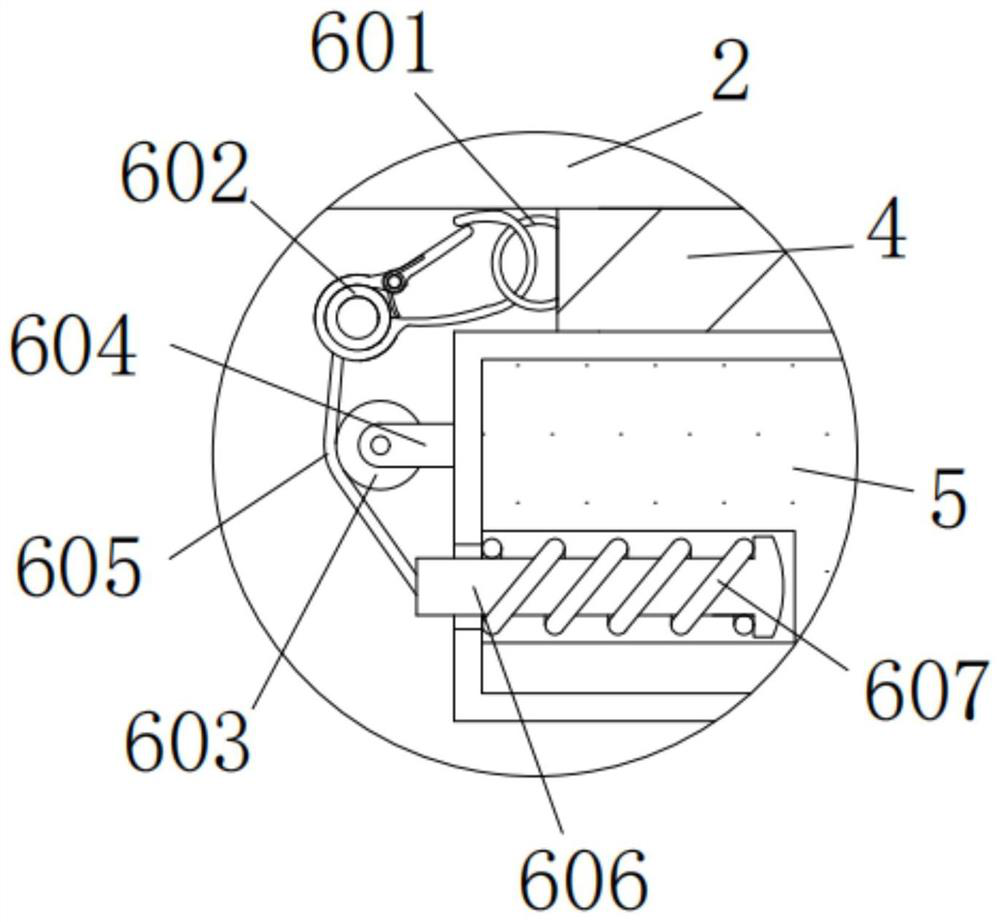
[0038] As an option, see Figure 1-3 , a transformer, both sides of the base 5 are provided with a fixing device 6, the fixing device 6 includes a ring 601, a buckle 602, a round wheel 603, a horizontal plate 604, a thick rope 605, a thick rod 606 and a first spring 607, The right end of the ring 601 is fixedly connected to the left side of the wide plate 4, and the inner wall of the ring 601 is movably connected with the inner wall of the buckle 602. The buckle 602 can be clamped inside the ring 601 for fixing, and the buckle can be fastened during transportation. 602 is removed to achieve separation. The bottom of the buckle 602 is provided with a thick rope 605. The bottom of the thick rope 605 is fixedly connected to the left bottom of the buckle 602. The right side of the thick rope 605 is attached to the left side of the round wheel 603. , the front of the round wheel 603 is connected to the left side of the rear end surface of the horizontal plate 604 through the pin sh...
Embodiment 3
[0041] As an option, see figure 1 , 2 And 4, a transformer, the inside of the housing 2 is provided with a cooling device 3, the cooling device 3 includes a bracket 301, a water pump 302, a ring pipe 303, a cooling plate 304 and a short plate 305, the bottom of the bracket 301 is connected to the bottom of the inner wall of the housing 2 to the left The side is fixedly connected, the model of the water pump 302 is 100WQ65-22-7.5, the top of the bracket 301 is fixedly connected with the bottom of the water pump 302, the output end of the water pump 302 is connected with the lower right side of the transformer 1, and the input end of the water pump 302 is connected with the ring pipe The left side of the bottom of 303 is fixedly connected. The transformer 1 uses the oil immersion method for heat dissipation. The coolant in the transformer 1 is sucked out by the water pump 302 and cooled by the cooling plate 304, and then transported to the transformer 1 for heat dissipation. The...
PUM
 Abstract
Description
Claims
Application Information
 - R&D
- Intellectual Property
- Life Sciences
- Materials
- Tech Scout
- Unparalleled Data Quality
- Higher Quality Content
- 60% Fewer Hallucinations
Browse by: Latest US Patents, China's latest patents, Technical Efficacy Thesaurus, Application Domain, Technology Topic, Popular Technical Reports.
© 2025 PatSnap. All rights reserved.Legal|Privacy policy|Modern Slavery Act Transparency Statement|Sitemap|About US| Contact US: help@patsnap.com


