A Double Hole Coprime Array Antenna Structure

An array antenna and antenna structure technology, applied in the field of dual-hole coprime array antenna structure, can solve problems such as loss of degrees of freedom, reduce the number of antenna elements, improve angle estimation performance and spatial resolution, and have flexible and simple antenna layouts. Effect

Active Publication Date: 2021-07-20
NANJING UNIV OF AERONAUTICS & ASTRONAUTICS
View PDF3 Cites 0 Cited by
  • Summary
  • Abstract
  • Description
  • Claims
  • Application Information

AI Technical Summary

Problems solved by technology

However, the difference co-array (Difference co-array) produced by the existing coprime array (Difference co-array), that is, the virtual array, the existing holes lead to a lot of loss of available degrees of freedom

Method used


Image

  • A Double Hole Coprime Array Antenna Structure
  • A Double Hole Coprime Array Antenna Structure
  • A Double Hole Coprime Array Antenna Structure

Examples


Embodiment Construction

[0022] The present invention is described in further detail now in conjunction with accompanying drawing.

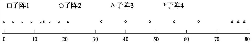
[0023] The invention discloses a Coprime array with a two-hole difference co-array (CATHDC) antenna structure. The structure is composed of four sparse sub-arrays, the total number of array elements is T, and the number of antennas is N, and M, wherein N and M=3 are coprime integers, M in and d≤λ / 2 is the unit array element spacing, λ is the carrier wavelength,

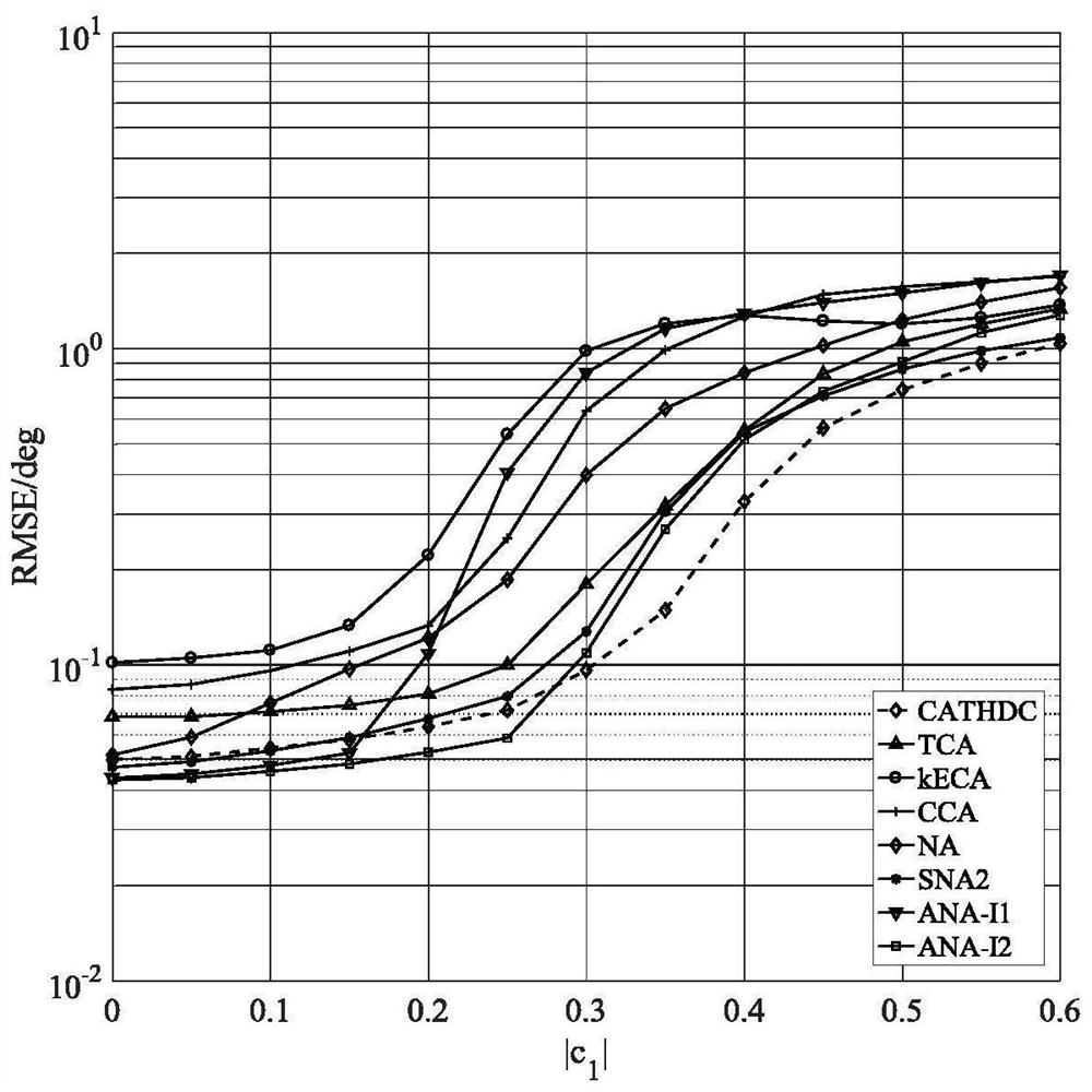
[0024] Table 1 shows the parameters of the relevant sparse array structure required by this patent, including array layout, continuous DOF ​​(uDOF), weight function w(1), w(2), w(3) and coupling rate, where TCA represents de Redundant coprime array (thinned coprime array), kECA is k-time extended coprime array (k-time extended coprime array), CCA is complementary coprime array (complementary coprime array), NA is two-level nested array (nested array) ), SNA2 is a 2-order super nested array (2-order sup...


PUM


Abstract

A dual-hole coprime array antenna structure is composed of four sparse subarrays, the total number of array elements is T, and the number of antennas are N and M respectively, wherein N and M are coprime integers, and M<N. The position of the array elements in the CATHDC antenna structure is where d≤λ / 2 is the unit array element spacing, and λ is the carrier wavelength. The antenna structure of the present invention expands the antenna aperture and weakens the mutual coupling effect. The antenna array layout is simple and can Gain more degrees of freedom than existing coprime arrays. The virtual array generated by CATHDC is a uniform array with unit element spacing, and the classical signal angle of arrival estimation algorithm combined with the spatial smoothing method can be directly applied without angle ambiguity.

Description

technical field [0001] The invention belongs to the field of array antenna layout, and in particular relates to a dual-hole coprime array antenna structure. Background technique [0002] The traditional antenna layout is limited by the half-wavelength, that is, the distance between the array elements is smaller than half-wavelength. Therefore, when the number of antennas is fixed, the aperture of the antenna is limited. At the same time, small array elements will also lead to a strong mutual coupling effect between antenna elements. In addition, the number of targets that can be identified by traditional DOA estimation algorithms is limited by the number of antenna elements in the physical array, that is, degrees of freedom. When the number of targets exceeds the number of antenna elements, many algorithms will fail. [0003] At present, a kind of antenna structure layout called coprime array has received extensive attention. Its element spacing breaks through the half-wav...

Claims


Application Information

Patent Timeline
Patent Type & Authority Patents(China)
IPC IPC(8): H01Q21/00H01Q1/36H01Q3/00H01Q3/02
CPCH01Q1/36H01Q3/005H01Q3/02H01Q21/00
Inventor 郑旺张小飞李建峰
Owner NANJING UNIV OF AERONAUTICS & ASTRONAUTICS
Why Eureka
Try Eureka