Magnesium alloy plate stamping device

A stamping device and technology for magnesium alloy plates, applied in the field of magnesium alloy plate stamping, can solve the problems of magnesium alloy template deformation, low precision, low yield, etc., and achieve the effects of facilitating loading and unloading operations, ensuring stamping quality, and improving production efficiency

Pending Publication Date: 2021-01-05
巢湖云海镁业有限公司
View PDF6 Cites 7 Cited by
  • Summary
  • Abstract
  • Description
  • Claims
  • Application Information

AI Technical Summary

Problems solved by technology

[0005] Aiming at the deficiencies of the prior art, the present invention provides a magnesium alloy sheet stamping device, which has the advantages of being able to realize relatively continuous stamping operations, improving production efficiency, and being convenient for people to perform loading and unloading operations, ensuring the safety of loading and unloading , to solve the problem that the accuracy is very low when processing larger-sized profiles, and the size and spacing of the holes are completely dependent on the meter scale measurement, and the hole is drilled with a hand-held drilling device, which makes it difficult to accurately control the size and spacing of the holes. Applicable finished products The rate is low, and the magnesium alloy template is prone to deformation during the drilling process. When the deformation of the magnesium alloy template reaches a certain level, the magnesium alloy template will be scrapped, thus causing a high scrap rate of the magnesium alloy template.

Method used


Image

  • Magnesium alloy plate stamping device
  • Magnesium alloy plate stamping device
  • Magnesium alloy plate stamping device

Examples


Embodiment Construction

[0024]The technical solutions in the embodiments of the present invention will be described clearly and completely below. Obviously, the described embodiments are only a part of the embodiments of the present invention, rather than all the embodiments. Based on the embodiments of the present invention, all other embodiments obtained by those of ordinary skill in the art without creative work shall fall within the protection scope of the present invention.

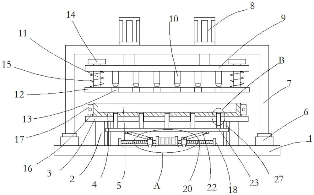
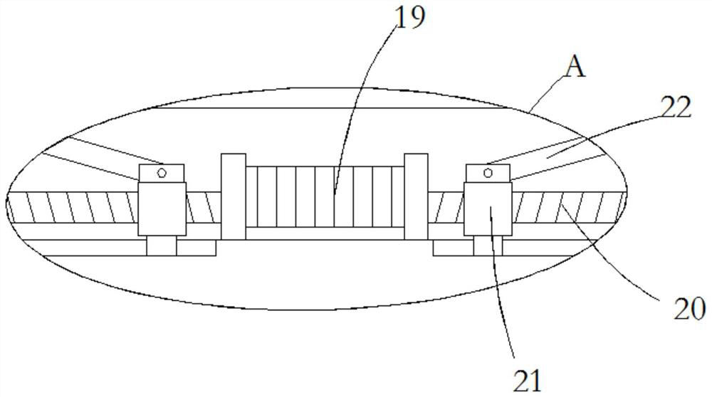
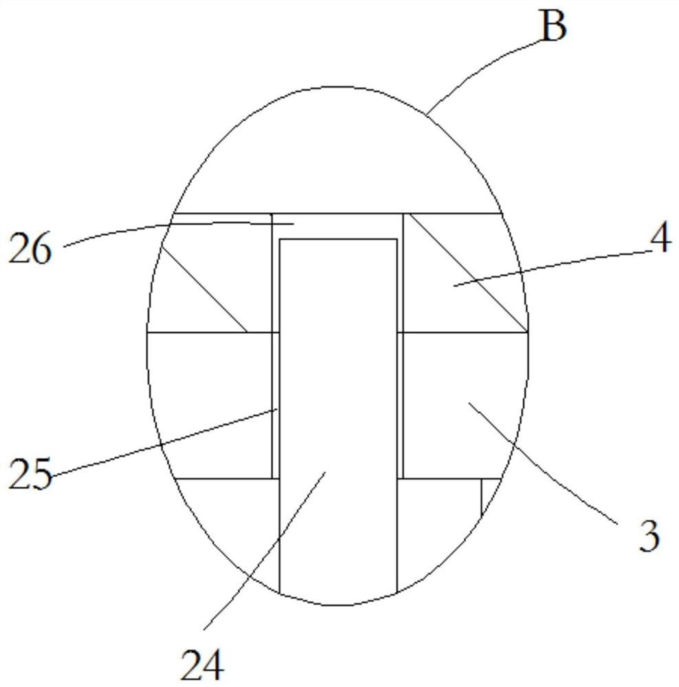
[0025]SeeFigure 1-4, A magnesium alloy plate stamping device, comprising a base 1. The upper end of the base 1 is symmetrically fixedly connected with a plurality of supporting blocks 2, the upper ends of the plurality of supporting blocks 2 are fixedly connected to the same pallet 3, and the upper ends of the pallet 3 are fixedly connected There is a lower mold 4, the upper end of the lower mold 4 is symmetrically opened with two mold slots 5 front and rear, the upper end of the base 1 is fixedly connected with two electric slide r...


PUM


Abstract

The invention relates to the technical field of magnesium alloy plate stamping, and discloses a magnesium alloy plate stamping device. The magnesium alloy plate stamping device comprises a base, a plurality of supporting blocks are symmetrically and fixedly connected to the upper end of the base, the upper ends of the supporting blocks are fixedly connected with the same support plate, the upper end of the support plate is fixedly connected with a lower die, and two die grooves are formed in the upper end of the lower die in a front-back symmetrical mode; two electric sliding rails are fixedlyconnected to the upper end of the base in a bilateral symmetry mode, sliding blocks on the two electric sliding rails are fixedly connected with the same U-shaped supporting plate, two air cylindersare symmetrically and fixedly connected to the upper end of the horizontal portion of the U-shaped supporting plate, and output shafts at the lower ends of the two air cylinders penetrate through thelower end of the horizontal portion of the U-shaped supporting plate and are fixedly connected with the same stamping plate; and a plurality of stamping heads are uniformly and fixedly connected to the lower end of the p stamping plate. The magnesium alloy plate stamping device has the advantages that continuous stamping operation can be achieved, the production efficiency is improved, people canconduct feeding and discharging operation conveniently, and the feeding and discharging safety is guaranteed.

Description

Technical field[0001]The invention relates to the technical field of magnesium alloy plate stamping, in particular to a magnesium alloy plate stamping device.Background technique[0002]At present, the pattern of modular steel formwork in China has been broken. The development of new formwork, especially aluminum formwork is fast, but the weight of a single aluminum alloy formwork is still as much as 30 kg. In addition, because aluminum alloy is medium Metals, aluminum alloys are prone to corrosion in an alkaline concrete environment, causing potholes and pockmarked surfaces on the concrete surface. The density of magnesium alloys is only two-thirds of that of aluminum alloys. Due to the advantages of light weight, magnesium alloys Magnesium alloys will have great advantages when used in building templates, but the use of magnesium alloys to make building templates has the following problems:[0003]The hot extrusion technology level of magnesium alloy is born out of aluminum alloy hot ...

Claims


Application Information

Patent Timeline
Patent Type & Authority Applications(China)
IPC IPC(8): B21D28/26B21D45/04B21D43/00B21D37/10
CPCB21D28/26B21D45/04B21D43/003B21D37/10
Inventor 王青锋马香亮
Owner 巢湖云海镁业有限公司
Why Eureka
Try Eureka