
Full-automatic tool jig for precision lathe

A technology of tooling fixtures and precision lathes, which is applied in the field of fully automatic tooling fixtures for precision lathes, can solve problems such as low production efficiency, lower lathe processing efficiency, and high cost, so as to reduce labor intensity, improve automation and practicability Effect

Active Publication Date: 2021-01-05
浙江众兴智能科技股份有限公司
View PDF7 Cites 2 Cited by
  • Summary
  • Abstract
  • Description
  • Claims
  • Application Information

AI Technical Summary

Problems solved by technology

Ordinary lathes are mainly manually operated by workers, and the production efficiency is low. It is suitable for single-piece, small-batch production and repair workshops
[0003] The lathes in the prior art require workers to operate manually, including loading and unloading, clamping and processing, which makes the labor intensity of the workers high. At the same time, the processing of a part needs rough machining and finishing machining, and it needs to be replaced when machining the side and end faces. cutting tool, resulting in the need for multiple lathes to work together, which takes a lot of time for clamping and reduces the processing efficiency of the lathe

Method used


Image

  • Full-automatic tool jig for precision lathe
  • Full-automatic tool jig for precision lathe
  • Full-automatic tool jig for precision lathe

Examples


Embodiment Construction

[0031]The technical solutions in the embodiments of the present invention will be clearly and completely described below in conjunction with the accompanying drawings in the embodiments of the present invention. Obviously, the described embodiments are only a part of the embodiments of the present invention, rather than all the embodiments. Based on the embodiments of the present invention, all other embodiments obtained by those of ordinary skill in the art without creative work shall fall within the protection scope of the present invention.

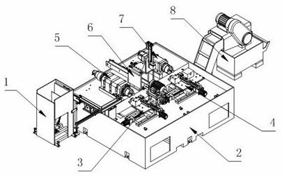
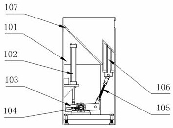
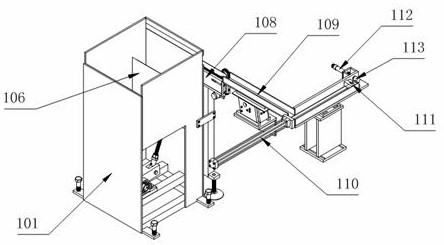
[0032]As attachedFigure 1-8The automatic tooling jig for a precision lathe shown includes an automatic feeding mechanism 1, a device working table 2 is arranged on the side of the automatic feeding mechanism 1, and a rough turning tool holder is fixed on the upper surface of the device working table 2 Mechanism 3 and fine turning tool post movement mechanism 4, the other side of the upper surface of the device worktable 2 is fixedly installed w...


PUM


Abstract

The invention discloses a full-automatic tool jig for a precision lathe, and particularly relates to the technical field of lathe machining devices. The full-automatic tool jig comprises an automaticfeeding mechanism. A device working table is arranged beside the automatic feeding mechanism. A rough turning tool rest moving mechanism and a finish turning tool rest moving mechanism are fixedly installed on one side of the upper surface of the device working table. A rough turning spindle module, an automatic material taking and placing mechanism and a finish turning spindle module are fixedlyinstalled on the other side of the upper surface of the device working table. An automatic material collecting mechanism is arranged beside the device working table. According to the full-automatic tool jig for the precision lathe, by arranging the automatic feeding mechanism, the rough turning tool rest moving mechanism, the finish turning tool rest moving mechanism, the rough turning spindle module, the automatic taking and placing mechanism, the finish turning spindle module and the automatic material collecting mechanism, the full-automatic production functions of feeding, machining, material taking and placing, recycling and storing of parts by the device are achieved, the labor intensity of workers is reduced, and the automation degree and the practicability of the device are improved.

Description

Technical field[0001]The present invention relates to the technical field of lathe processing devices, and more specifically, the present invention relates to a fully automatic tooling jig for precision lathes.Background technique[0002]A lathe is a machine tool that mainly uses a turning tool to turn a rotating workpiece. Drills, reamers, reamers, taps, dies and knurling tools can also be used on the lathe for corresponding processing. The lathe has a wide range of processing objects, and the adjustment range of the spindle speed and feed is large, and it can process the inner and outer surfaces, end faces, and inner and outer threads of the workpiece. Ordinary lathes are mainly operated by workers manually, with low production efficiency, and are suitable for single-piece, small batch production and repair workshops.[0003]The lathe in the prior art requires manual operations by workers, including loading and unloading, clamping and processing, which makes the workers labor intensiv...

Claims


Application Information

Patent Timeline
Patent Type & Authority Applications(China)
IPC IPC(8): B23Q7/00B23Q7/04B23Q7/06B23Q7/18
CPCB23Q7/003B23Q7/18B23Q7/06B23Q7/008B23Q7/04
Inventor 刘景全
Owner 浙江众兴智能科技股份有限公司
Learn More