Clamping assembly for producing copper pipe

A technology for clamping components and copper tubes, which is applied in vices, manufacturing tools, etc., can solve problems such as inability to fix clamps, copper tube rotation, and insufficient clamping of copper tubes, so as to avoid clamp shaking, increase friction, and replace Convenient and fast effect

Active Publication Date: 2021-01-05
江西九星铜业有限公司
View PDF16 Cites 2 Cited by
  • Summary
  • Abstract
  • Description
  • Claims
  • Application Information

AI Technical Summary

Problems solved by technology

[0004] The above-mentioned patent also has the following disadvantages: the clamping of the copper tube is not stable enough, which may cause the copper tube to rotate, and the clamp cannot be fixed

Method used


Image

  • Clamping assembly for producing copper pipe
  • Clamping assembly for producing copper pipe
  • Clamping assembly for producing copper pipe

Examples


Embodiment 1

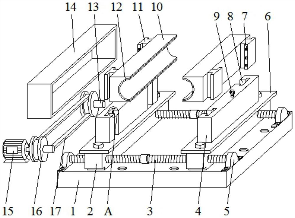
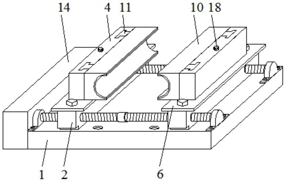
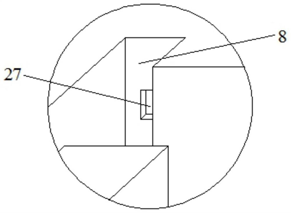
[0028] refer to Figure 1-4 , a clamping assembly for producing copper pipes, including a base plate 1, a box body 14 and a slide plate 2, the box body 14 is welded horizontally to one side of the base plate 1, and there are two slide plates 2 that are horizontally slidably connected to the top of the base plate 1, and the base plate The top of 1 is equipped with a synchronous movement mechanism for synchronously moving the two slides 2, and the structures of the tops of the two slides 2 are identical and symmetrically arranged, and the top of the slides 2 is horizontally connected with a top plate 6 by bolts, and the center of the top of the top plate 6 is welded vertically There is a hollow plate 4, one side of the hollow plate 4 is slidably connected with a fixture 10, and both ends of the fixture 10 close to the hollow plate 4 are vertically welded with T-shaped blocks 11, and the two ends of the side of the hollow plate 4 close to the fixture 10 There are T-shaped slots 8...

Embodiment 2

[0037] refer to Figure 5 , a clamping assembly for producing copper pipes. Compared with Embodiment 1, this embodiment differs only in that the rotating mechanism includes a first gear 19, and there are two first gears 19 that are vertically rotatably connected to the box body 14 Inside, the same second gear 20 is meshed between the opposite sides of the two first gears 19, and the second gear 20 is vertically rotatably connected to the inside of the box body 14, and a second positive and negative gear is installed horizontally on one side of the box body 14. motor 21, and the top end of the output shaft of the second reversible motor 21 is welded to the center of one side of the second gear 20.

[0038] The working principle of this embodiment: in actual use, the second gear 20 is driven to rotate by the second positive and negative motor 21, the second gear 20 drives the two first gears 19 to rotate, and the two first gears 19 drive the two rotating rods 13 rotates, the tw...


PUM


Abstract

The invention belongs to the technical field of copper pipe production, particularly relates to a clamping assembly for producing a copper pipe, and aims at solving the problems that the clamping of the copper pipe is not stable enough and a clamp cannot be fixed. According to the scheme, the clamping assembly comprises a bottom plate, a box body and sliding plates, wherein the box body is horizontally welded on one side of the bottom plate. the two sliding plates are both horizontally connected to the top of the bottom plate in a sliding mode, a synchronous moving mechanism used for synchronously moving the two sliding plates is arranged at the top of the bottom plate, the tops of the two sliding plates are completely the same in structure and are symmetrically arranged, a top plate is horizontally connected at the tops of the sliding plates through bolts, a hollow plate is vertically welded to the center of the top of the top plate, a clamp is slidably connected to one side of the hollow plate, and T-shaped blocks are vertically welded to the two ends of the side, close to the hollow plate, of the clamp. According to the clamping assembly, the copper pipe is prevented from rotating, so that the quality of the copper pipe during production is improved.

Description

technical field [0001] The invention relates to the technical field of copper pipe production, in particular to a clamping assembly for producing copper pipes. Background technique [0002] Copper tubes are also called copper tubes. A type of non-ferrous metal pipe, which is a pressed and drawn seamless pipe. Copper pipe has good electrical conductivity and thermal conductivity, and is the main material of conductive accessories and heat dissipation accessories of electronic products, and has become the first choice for modern contractors to install tap water pipes, heating and cooling pipes in all residential commercial buildings. Copper tubes have strong corrosion resistance, are not easy to oxidize, and are not easy to chemically react with some liquid substances, and are easy to bend. [0003] After searching, the Chinese patent authorization number is CN207139354U, which discloses a copper tube clamping device, and the clamping position can also be fine-tuned by adjus...

Claims


Application Information

Patent Timeline
Patent Type & Authority Applications(China)
IPC IPC(8): B25B1/02B25B1/10B25B1/20
CPCB25B1/02B25B1/10B25B1/20
Inventor 王浩臣黄细耿永怀康艳华
Owner 江西九星铜业有限公司
Why Eureka
Try Eureka