Polyurethane foam composite board, preparation system and preparation process

A polyurethane foam and composite board technology, which is applied to flat products, climate change adaptation, household appliances, etc., can solve the problems of extruding triangular prism grooves, bonding polyurethane foam boards, etc., and achieve the effect of easy bonding

Active Publication Date: 2021-01-05
九焱新材料(深圳)有限公司
View PDF13 Cites 1 Cited by
  • Summary
  • Abstract
  • Description
  • Claims
  • Application Information

AI Technical Summary

Problems solved by technology

However, this patent cannot press out multiple triangular prism-shaped grooves on the metal plate, and cannot facilitate the firm bonding of the polyurethane foam plate to the metal plate

Method used


Image

  • Polyurethane foam composite board, preparation system and preparation process
  • Polyurethane foam composite board, preparation system and preparation process
  • Polyurethane foam composite board, preparation system and preparation process

Examples


specific Embodiment approach 1

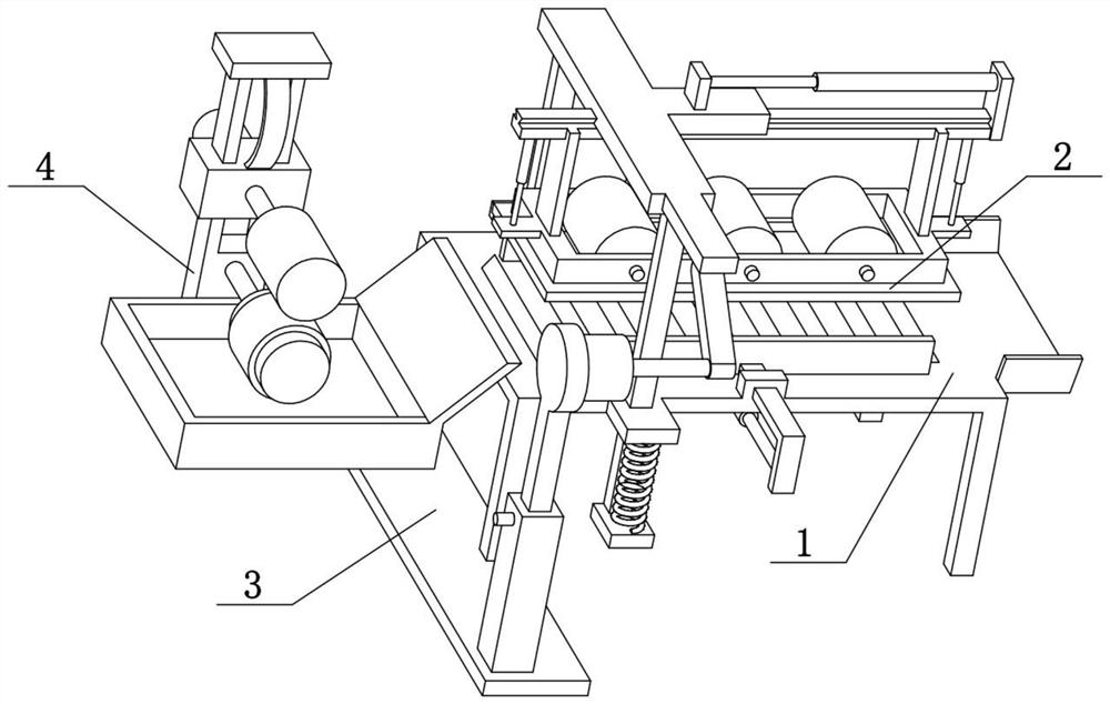
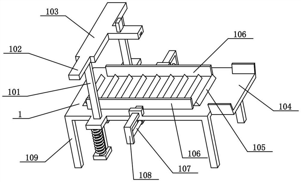
[0034] Combine below Figure 1-9 Describe this embodiment, the present invention relates to the field of composite board preparation, more specifically a polyurethane foam composite board preparation system, including a flat plate 1, a limiting groove plate 104, a triangular rib 105, a retaining bar 106, and an electric push rod I107 , L-shaped column 108 and support column 109, the present invention can press out a plurality of triangular prism-shaped grooves on the metal plate, thereby facilitating the firm adhesion of the polyurethane foam plate to the metal plate.

[0035]The right end of the flat plate 1 is fixedly connected to the limited groove plate 104, and the four corners of the lower side of the flat plate 1 are fixedly connected with support columns 109, and the upper side of the flat plate 1 is evenly distributed with a plurality of triangular ribs 105 from left to right, One is provided at the front and rear of the retaining bars 106, and the outer sides of the ...

specific Embodiment approach 2

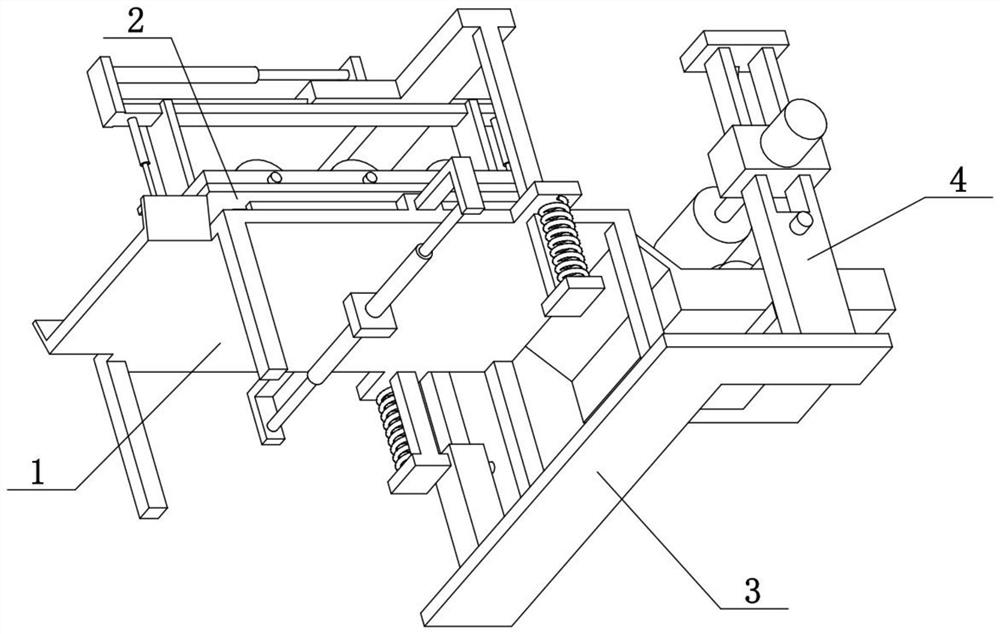
[0037] Combine below Figure 1-9 To illustrate this embodiment, the polyurethane foam composite sheet preparation system also includes a pressing frame 2, a rotating roller 201, an electric push rod II202, a vertical bar 203, a top beam 205, a rectangular frame 207 and a rectangular hole 208, and the pressing frame 2 is arranged on On the top of the plate 1, the pressure frame 2 is provided with a rectangular hole 208, and the left and right ends of the upper side of the pressure frame 2 are fixedly connected with vertical bars 203, and the left and right ends of the rectangular frame 207 are respectively vertically slidably connected to the two vertical bars. On the rod 203, a plurality of rotating rollers 201 are connected to the rectangular frame 207 rotating from left to right, and a top beam 205 is fixedly connected between the upper ends of the two vertical bars 203, and the left and right ends of the top beam 205 are fixedly connected with The electric push rod II202, t...

specific Embodiment approach 3

[0039] Combine below Figure 1-9 To illustrate this embodiment, the polyurethane foam composite sheet preparation system also includes a vertical column 101, a top plate 103, a trapezoidal slide rail 204 and an electric push rod III206, and the front and rear ends of the lower side of the top plate 103 are fixedly connected with the vertical column 101, Two vertical moving columns 101 are respectively vertically slidably connected to the front and rear ends of the flat panel 1, and the upper side of the top beam 205 is provided with a trapezoidal slide rail 204, and the trapezoidal slide rail 204 is slidably connected to the top plate 103 in the left and right direction, and the top beam 205 The right part of the electric push rod III206 is fixedly connected with the electric push rod III206, and the left end of the electric push rod III206 is fixedly connected on the top plate 103. The two vertical moving columns 101 can slide vertically on the flat plate 1, and then drive th...


PUM


Abstract

The invention relates to the field of composite board preparation, in particular to a polyurethane foam composite board, a preparation system and a preparation process. The process comprises the following steps that S1, a metal plate is placed on the upper sides of a plurality of triangular convex edges on a flat plate, so that two barrier strips block the front side and the rear side of the metalplate correspondingly; S2, when a pressing frame is pressed downwards, the pressing frame can be pressed on the metal plate, and then a plurality of triangular-prism-shaped grooves are formed in themetal plate by pressing by the aid of the plurality of triangular convex edges; S3, the lower portions of multiple rotating rollers are moved to the lower side of the pressing frame, then the multiplerotating rollers are driven to roll left and right on the metal plate when the pressing frame moves left and right, and then the triangular convex edges are further pressed on the metal plate; and S4, the metal plate subjected to groove pressing enters the upper portion of a lower rotating wheel, when the metal plate continuously moves leftwards, the lower rotating wheel and felt are driven to rotate, mucilage glue is added into a groove box, the felt rotates to roll up the mucilage glue, and the felt smears the mucilage glue on the plurality of triangular-prism-shaped grooves in the lower side of the metal plate.

Description

technical field [0001] The invention relates to the field of composite sheet preparation, and more specifically relates to a polyurethane foam composite sheet, a preparation system and a preparation process. Background technique [0002] The application number is CN200910090090.7, which discloses a polyurethane foam composite board and its preparation method. The invention discloses a polyurethane foam composite board, which consists of a panel and a composite core board. Light plane damping plate and porous damping plate arranged in a regular square or triangular manner. The composite core plate is formed by bonding one side of the open-cell polyurethane molding plate and the porous damping plate to form a single-sided core plate. The single-sided core plate and the light plane damping panel are in In the forming mold, the two-component polyurethane foam composite materials A and B are foamed and cured to form a multi-layer structure composite, and the polyurethane foam com...

Claims


Application Information

Patent Timeline
IPC IPC(8): B29C65/52B29L7/00B29L9/00
CPCB29C65/526B29C66/0222B29C66/742B29L2007/002B29L2009/003Y02A40/25
Inventor 刘长乐
Owner 九焱新材料(深圳)有限公司
Why Eureka
Try Eureka