Shockproof vehicle-mounted WiFi device

A technology of equipment and slide rails, applied in mechanical equipment, vehicle parts, springs/shock absorbers, etc., can solve problems such as limited gas filling, reduced protection effect, device damage, etc., to achieve the effect of promoting air flow

Pending Publication Date: 2021-01-05
郭发有
View PDF2 Cites 2 Cited by
  • Summary
  • Abstract
  • Description
  • Claims
  • Application Information

AI Technical Summary

Problems solved by technology

[0002] Chinese patent (CN107276610A) discloses a vehicle-mounted WiFi network communication device, including a bottom plate, the bottom of the bottom plate is made of non-slip material, side plates are provided on both sides of the bottom plate, and four rollers are arranged on the upper part of each side plate opposite to each other; The above-mentioned patent solution has the following disadvantages: the car is prone to bumps during operation, and the device fixed on the car will also bump with the car at this time, and the device will be damaged during the bumping process, which will affect the device in the long

Method used


Image

  • Shockproof vehicle-mounted WiFi device
  • Shockproof vehicle-mounted WiFi device
  • Shockproof vehicle-mounted WiFi device

Examples


Embodiment 1

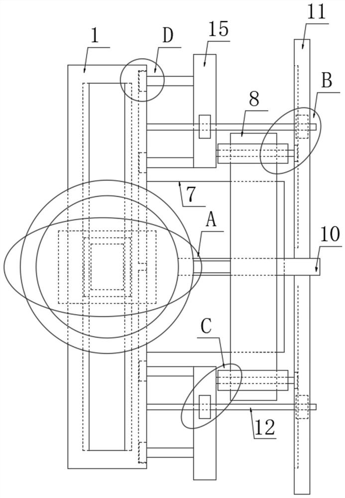
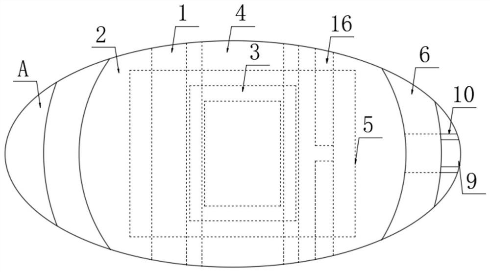
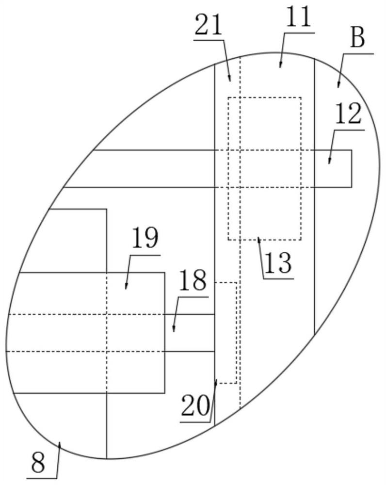
[0029] refer to Figure 1-5 , a shockproof vehicle-mounted WiFi device, comprising a slide rail 1, a slide block 2, a WiFi transmitter 5, an elastic airbag 6 is fixedly sleeved on the outer wall of the WiFi transmitter 5, and the elastic airbag 6 is provided with an annular seal, and the slide rail 1 Support plate 7 is fixedly installed on the right side of the support plate 7, and rubber air bag 8 is fixedly installed on the support plate 7. Gas is filled in the elastic air bag 6 and rubber air bag 8, and the elastic air bag 6 and the rubber air bag 8 are fixedly connected and elastic. tube 9;

[0030] The above points worth noting are as follows:

[0031] 1. The gas filled in the elastic air bag 6 and the rubber air bag 8 is preferably air, and gases such as nitrogen can also be used.

[0032] 2. The elastic airbag 6 is annularly sealed and does not have tiny air holes, so it is determined that there will be no rapid leakage of gas when relatively violent turbulence occurs...

Embodiment 2

[0048] refer to Figure 6 , the difference between this embodiment and the first embodiment is that: both ends of the slide rail 1 are fixedly installed with a piston cylinder 23 through a rod frame 22, the piston cylinder 23 includes a piston rod 24 and a piston, and the piston rod 24 is far away from the piston One end of it is fixedly installed on the corresponding tooth plate two 15.

[0049] The advantage of the second embodiment over the first embodiment is that when the second tooth plate 15 moves, it will drive the corresponding piston rod 24 to move, and the reciprocating movement of the piston rod 24 is used to realize the suction and exhaust operations in the piston barrel 23, thereby Significantly improves the air flow in the car.


PUM


Abstract

The invention provides a shockproof vehicle-mounted WiFi device which comprises a sliding rail, a sliding block and a WiFi emitter, the outer wall of the WiFi emitter is fixedly sleeved with an elastic air bag, the elastic air bag is arranged in an annular sealing mode, a supporting plate is fixedly installed on the right side face of the sliding rail, a rubber air bag is fixedly installed on thesupporting plate, and an elastic pipe is fixedly communicated between the elastic air bag and the rubber air bag. The shockproof vehicle-mounted WiFi device has the advantages that when a sliding block rapidly moves due to violent jolt, gas in the rubber air bag can be rapidly extruded into the elastic air bag and expands to protect the sliding block, the elastic air bag is arranged in an annularsealing mode and is not provided with fine air holes, and it is determined that rapid gas leakage does not occur when violent jolt occurs; meanwhile, a toothed plate II moves to drive a correspondingpiston rod to move, and air suction and exhaust operations in a piston cylinder can be realized by utilizing the reciprocating motion of the piston rod, so that the air flow in the vehicle can be obviously promoted.

Description

technical field [0001] The invention relates to a vehicle-mounted device, in particular to a shockproof vehicle-mounted WiFi device. Background technique [0002] Chinese patent (CN107276610A) discloses a vehicle-mounted WiFi network communication device, including a bottom plate, the bottom of the bottom plate is made of non-slip material, side plates are provided on both sides of the bottom plate, and four rollers are arranged on the upper part of the opposite surface of each side plate; The above-mentioned patent solution has the following disadvantages: the car is prone to bumps during operation, and the device fixed on the car will also bump with the car at this time, and the device will be damaged during the bumping process, which will affect the device in the long run. The quality of your WiFi signal. [0003] After retrieval, the Chinese authorized invention patent with the patent number CN108545025B discloses a shockproof vehicle-mounted WiFi device, including a sl...

Claims


Application Information

Patent Timeline
IPC IPC(8): B60R11/02F16F15/023
CPCB60R11/02F16F15/023
Inventor 郭发有
Owner 郭发有
Why Eureka
Try Eureka