Radioactive wastewater treatment device

A technology for radioactive wastewater and treatment devices, which is applied in water/sewage treatment, radioactive pollutants, adsorbed water/sewage treatment, etc., can solve the problems of affecting treatment efficiency, inconvenient replacement, and weakened adsorption capacity of water treatment materials, so as to improve safety. sexual effect

Inactive Publication Date: 2021-01-05
高峰
View PDF7 Cites 1 Cited by
  • Summary
  • Abstract
  • Description
  • Claims
  • Application Information

AI Technical Summary

Problems solved by technology

[0003] There are still many deficiencies in the existing radioactive water treatment device adopting adsorption method and example exchange method in actual use, for example: (1) the water treatment material needs to be replaced after being used for a period of time, and the existing equipment is inconvenient when changing, Operators are easy to touch radioactive sewage; (2) The adsorption capacity of the water treatment material gradually weakens after being crushed, which affects the post-processing efficiency; (3) After the water treatment material is crushed, part of the material adheres to the inside of the device. Clean up, the debris will easily block the equipment after being accumulated many times

Method used


Image

  • Radioactive wastewater treatment device
  • Radioactive wastewater treatment device
  • Radioactive wastewater treatment device

Examples


Embodiment Construction

[0028] In order to make the purpose, technical solutions and advantages of the embodiments of the present invention more clear, the technical solutions in the embodiments of the present invention will be clearly and completely described below in conjunction with the drawings in the embodiments of the present invention.

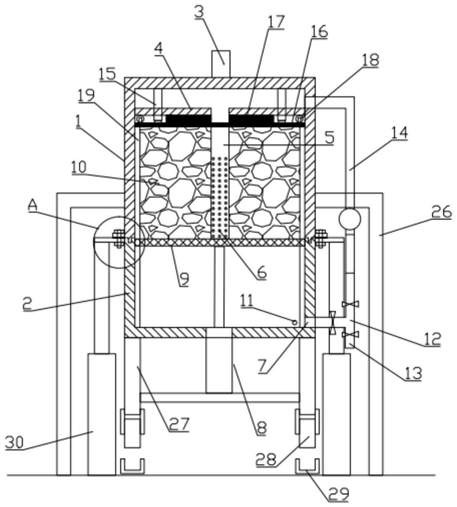
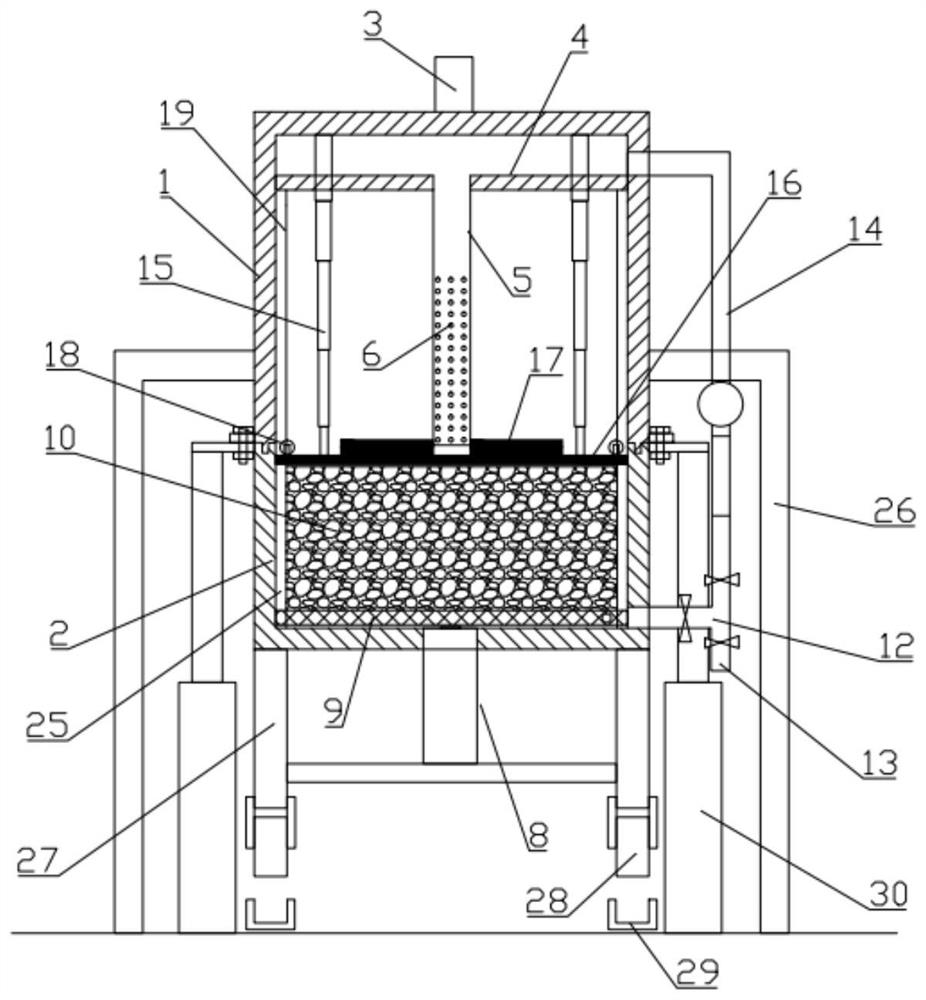
[0029] Such as Figure 1-5 In the shown embodiment, a radioactive wastewater treatment device includes a barrel body consisting of an upper barrel body 1 and a lower barrel body 2, wherein:

[0030] The upper end of the upper barrel body 1 is provided with a liquid inlet 3, and the middle and upper part of the inner cavity of the upper barrel body 1 is provided with a partition plate 4, and the partition plate 4 separates the upper barrel body 1 from top to bottom into a waste liquid buffer chamber and a waste liquid buffer chamber. In the waste liquid reaction chamber, a diversion tube 5 is arranged below the partition plate 4, the upper end of the diversion ...


PUM


Abstract

The invention relates to the technical field of wastewater treatment devices, in particular to a radioactive wastewater treatment device. The device comprises an upper barrel body and a lower barrel body, a partition plate is arranged on the upper middle portion of an inner cavity of the upper barrel body and divides the upper barrel body into a waste liquid buffer cavity and a waste liquid reaction cavity from top to bottom, a flow guide pipe is arranged below the partition plate, liquid discharging holes are evenly distributed in a flow guide pipe jet flow section, and a pushing and scrapingmechanism is further arranged at the upper end of the inner cavity of the upper barrel body. A first telescopic mechanism is fixed in the lower barrel body, the upper end of the first telescopic mechanism is fixedly connected with a pore plate, the pore plate is in contact with the flow guide pipe, a water treatment material is filled above the pore plate and below the pushing and scraping mechanism, a liquid outlet of the lower barrel body is communicated with an inlet of a three-way valve, one outlet of the three-way valve is connected with the starting end of a circulating pipeline, and the tail end of the circulating pipeline is communicated with the waste liquid buffer cavity. When the water treatment material is replaced, radioactive wastewater is not in contact with an operator, and crushed waste residues of the water treatment material can be cleaned up together.

Description

technical field [0001] The invention relates to the technical field of waste water treatment devices, in particular to a radioactive waste water treatment device. Background technique [0002] With the development of my country's nuclear industry, a large amount of radioactive waste has been produced, a large part of which is radioactive wastewater. The treatment methods of radioactive wastewater include adsorption method, ion exchange method, evaporation method, flocculation precipitation method and so on. When the adsorption method and ion exchange method use zeolite, activated carbon, ion exchange resin and other water treatment materials, the wastewater flow will easily crush these materials, so these materials are usually put into filter bags in the radioactive wastewater treatment process to facilitate loading and unloading of filter materials . [0003] There are still many deficiencies in the existing radioactive water treatment device adopting adsorption method an...

Claims


Application Information

Patent Timeline
Patent Type & Authority Applications(China)
IPC IPC(8): C02F1/28C02F1/42C02F101/00
CPCC02F1/28C02F1/281C02F1/283C02F1/42C02F2101/006C02F2201/002C02F2201/004C02F2201/005C02F2303/16C02F2303/14C02F2301/046
Inventor 高峰乔冕史蕾
Owner 高峰
Why Eureka
Try Eureka