


Quick Research
Generate reliable direction feasibility study reports for your R&D in just a few steps.

Technical Q&A
Discover and master advanced knowledge NOW. Basics, ideas, possibilities, all at once.

Find Solutions
As an expert in R&D theories, this can generate solutions to your technical problems instantly.

Evaluate Feasibility
Analyze your overall solution with one click, know your potential R&D risks in advance.

Monitor Landscape
Get weekly tech updates, stay abreast of the latest tech innovations and key insights.
Aeration device in biological aerated filter
An aerated biological filter and aeration device technology, applied in biological treatment devices, sustainable biological treatment, biological water/sewage treatment, etc., can solve the problem of oxygen transfer, incomplete mixing of gas and water, and inability to be affected by water flow or physical devices Cutting and other problems to achieve the effect of improving oxygen utilization and increasing transfer rate
- Summary
- Abstract
- Description
- Claims
- Application Information
AI Technical Summary
Problems solved by technology
Method used
Image

Examples
Embodiment 1
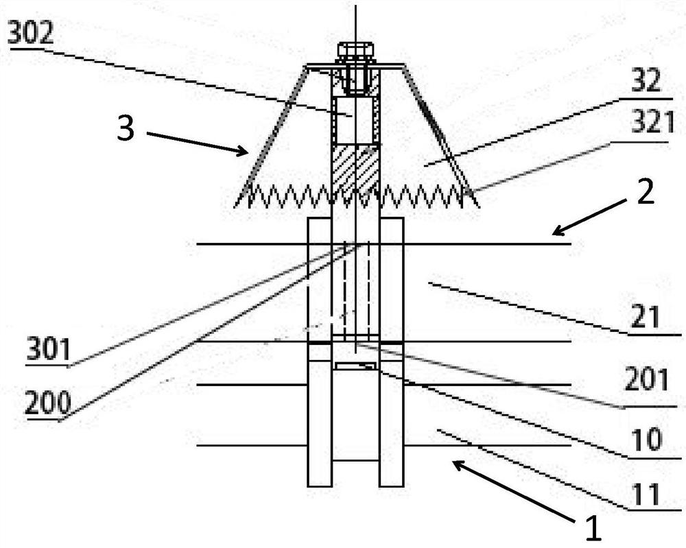
[0029] like figure 1 As shown, an aeration device in a biological aerated filter includes an aeration unit 1, a water distribution unit 2 and a diversion dispersion unit 3, and the water distribution unit 2 includes an upper water distribution hole 200 and a lower water distribution hole 201, The air distribution hole 10 of the aeration unit 1 is aligned with the lower water distribution hole 201 of the water distribution unit 2 , and the diversion dispersion unit 3 communicates with the upper water distribution hole 200 of the water distribution unit 2 .
[0030] Air passes through the air distribution hole 10 of the aeration unit 1 and enters the water distribution unit 2 through the lower water distribution hole 201 of the water distribution unit 2. The upper distribution water hole 200 of the unit 2 flows out and enters the diversion channel of the diversion dispersion unit 3 until it flows out from the diversion channel of the diversion unit 3; during this process, when t...
Embodiment 2
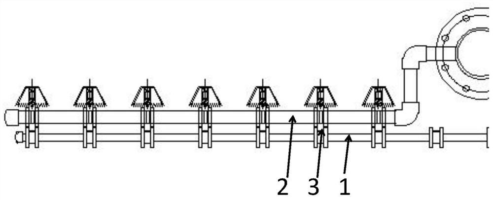
[0039] On the basis of Embodiment 1, multiple diversion and dispersion units 3 are provided, the diversion and dispersion units 3 communicate with the water distribution unit 2, and the aeration unit 1 corresponds to the diversion and dispersion units 3 one by one;
[0040] The air distribution branch pipes 11 of the aeration unit 1 are all connected with the air distribution main pipe, and the air distribution main pipe is connected with an aeration fan;
[0041] The water distribution branch pipes 21 of the water distribution unit 2 are all communicated with the water distribution main pipe, and the water distribution main pipe is connected with a water distributor.
[0042] During implementation, the aeration fan is used to aerate the air distribution main pipe, and the agitated air flows out from the air distribution hole 10 of the air distribution branch pipe, and enters the water distribution unit 2 through the lower water distribution hole 201 of the water distribution u...
PUM
 Abstract
Description
Claims
Application Information
 - R&D Engineer
- R&D Manager
- IP Professional
- Industry Leading Data Capabilities
- Powerful AI technology
- Patent DNA Extraction
Browse by: Latest US Patents, China's latest patents, Technical Efficacy Thesaurus, Application Domain, Technology Topic, Popular Technical Reports.
© 2024 PatSnap. All rights reserved.Legal|Privacy policy|Modern Slavery Act Transparency Statement|Sitemap|About US| Contact US: help@patsnap.com