
Glass cover plate and preparation method thereof, display panel and display device

A glass cover plate and ultra-thin glass technology, applied in glass manufacturing equipment, glass cutting devices, glass production, etc., can solve the problems of poor surface indexing and hardness, different distances, different thicknesses of functional layers, and different properties. Achieve the effect of improving production yield, good mechanical properties, and thinning

Pending Publication Date: 2021-01-05
XIAMEN TIANMA MICRO ELECTRONICS
View PDF8 Cites 3 Cited by
  • Summary
  • Abstract
  • Description
  • Claims
  • Application Information

AI Technical Summary

Problems solved by technology

[0003] Most of the glass cover plates in the prior art are composed of a glass substrate, and in order to improve the impact resistance of the glass cover plate, an explosion-proof film is usually added to the surface of the glass substrate, that is, the glass cover plate is composed of a glass substrate and an explosion-proof film; In this way, when the glass cover is applied to a display, it will be unfavorable for the thinning of the display, and the surface fingertips and hardness will be deteriorated
At the same time, when the glass cover is applied to a curved screen, the glass substrate of the glass cover is usually made into a curved surface, and then the corresponding functional film is formed on the surface of the glass substrate by deposition; however, since the glass substrate is The curved surface makes the angle and distance between the deposition source and each position on the surface of each glass substrate different, resulting in different thickness and properties of the functional layer deposited on the surface of the glass substrate, resulting in different optical properties of the functional film layer at each position on the glass cover plate , which reduces the production yield of the glass cover plate

Method used


Image

  • Glass cover plate and preparation method thereof, display panel and display device
  • Glass cover plate and preparation method thereof, display panel and display device
  • Glass cover plate and preparation method thereof, display panel and display device

Examples


preparation example Construction

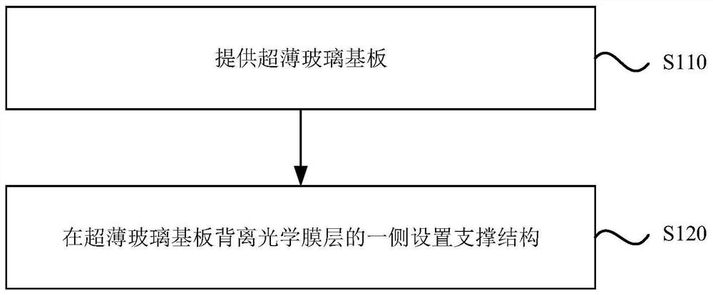
[0040] In order to solve the above technical problems, an embodiment of the present invention provides a method for preparing a glass cover, which is used to prepare the glass cover provided by the embodiment of the present invention. image 3 It is a flowchart of a method for preparing a glass cover plate provided by an embodiment of the present invention. Such as image 3 Shown, the preparation method of this glass cover plate comprises:

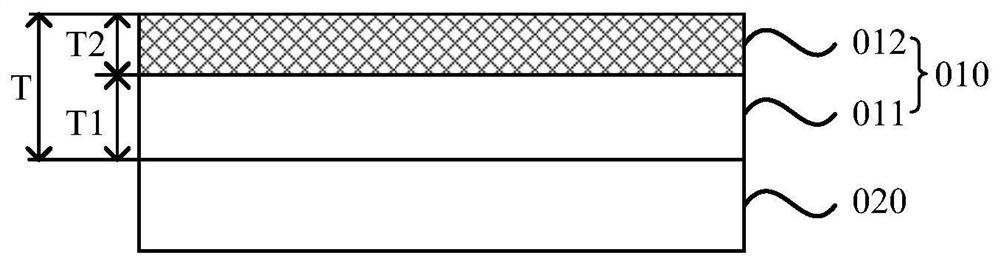
[0041] S110, providing an ultra-thin glass substrate; one side of the ultra-thin glass substrate is formed with an optical film layer in a roll-to-roll manner;

[0042] S120, setting a support structure on a side of the ultra-thin glass substrate away from the optical film layer.

[0043] in, Figure 4 With image 3 A structural schematic diagram of a corresponding preparation process of a glass cover plate. Such as Figure 4As shown, the ultra-thin glass substrate 11 is wound on the roller shaft 21 of the roll-to-roll equipment, and...


PUM


Abstract

The embodiment of the invention discloses a glass cover plate and a preparation method thereof, a display panel and a display device. The preparation method of the glass cover plate comprises the following steps: providing an ultra-thin glass substrate, wherein an optical film layer is formed on one side of the ultra-thin glass substrate in a roll-to-roll manner; and arranging a supporting structure on one side, deviating from the optical film layer, of the ultrathin glass substrate. According to the embodiment of the invention, the consistency of the optical performance of each position of the glass cover plate can be ensured so that the production yield of the glass cover plate can be improved; meanwhile, the display panel comprising the glass cover plate can be thinner so that the thinning of the display panel is facilitated.

Description

technical field [0001] Embodiments of the present invention relate to the field of display technology, and in particular to a glass cover plate and a manufacturing method thereof, a display panel and a display device. Background technique [0002] With the continuous development of display technology, displays are used more and more widely. Usually, a display is composed of a display module and a cover on the side of the display surface of the display module. The cover can protect the display module and optimize the display. Appearance. [0003] Most of the glass cover plates in the prior art are composed of a glass substrate, and in order to improve the impact resistance of the glass cover plate, an explosion-proof film is usually added to the surface of the glass substrate, that is, the glass cover plate is composed of a glass substrate and an explosion-proof film; In this way, when the glass cover plate is applied to a display, it will be unfavorable for the thinning of ...

Claims


Application Information

Patent Timeline
IPC IPC(8): C03C17/00C03B33/02G06F3/041G06F3/044
CPCC03C17/003C03C17/002C03B33/02G06F3/0412G06F3/0446G06F2203/04103Y02P40/57
Inventor 李征李小和张霄宁张育秦锋姬生超
Owner XIAMEN TIANMA MICRO ELECTRONICS
Features
  • Generate Ideas
  • Intellectual Property
  • Life Sciences
  • Materials
  • Tech Scout
  • Unparalleled Data Quality
  • Higher Quality Content
  • 60% Fewer Hallucinations
Learn More