
Hydraulically-controlled self-reversing gas pressurizing cylinder

A gas pressurization and self-reversing technology, applied in fluid pressure actuators, fluid pressure converters, servo motor components, etc., can solve unsatisfactory vibration and noise reduction effects, can not completely eliminate the risk of spark detonation, explosion-proof High cost and other problems, to achieve the effect of reducing engineering cost, increasing service life and improving safety

Active Publication Date: 2021-01-05
CHINA PETROCHEMICAL CORP +1
View PDF5 Cites 0 Cited by
  • Summary
  • Abstract
  • Description
  • Claims
  • Application Information

AI Technical Summary

Problems solved by technology

Existing hydraulic compressors generally use explosion-proof electromagnetic reversing valves to meet explosion-proof requirements. At the same time, forced buffering at the stroke end is used to reduce the impact of the pressurized cylinder to achieve the purpose of reducing vibration and noise. However, the explosion-proof cost is high and cannot be completely eliminated. The risk of electric spark detonation, and the effect of vibration and noise reduction is not ideal

Method used


Image

  • Hydraulically-controlled self-reversing gas pressurizing cylinder
  • Hydraulically-controlled self-reversing gas pressurizing cylinder
  • Hydraulically-controlled self-reversing gas pressurizing cylinder

Examples


Embodiment Construction

[0038] The present invention will be further described in detail below in conjunction with the accompanying drawings, so that those skilled in the art can implement it with reference to the description.

[0039] In the description of the present invention, the terms "transverse", "longitudinal", "upper", "lower", "front", "rear", "left", "right", "vertical", "horizontal", " The orientations or positional relationships indicated by "top", "bottom", "inner", "outer", etc. are based on the orientations or positional relationships shown in the drawings, and are only for the convenience of describing the present invention and simplifying the description, and are not indicative or implied. It should not be construed as limiting the invention that a device or element must have a particular orientation, be constructed, and operate in a particular orientation.

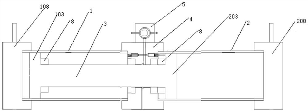
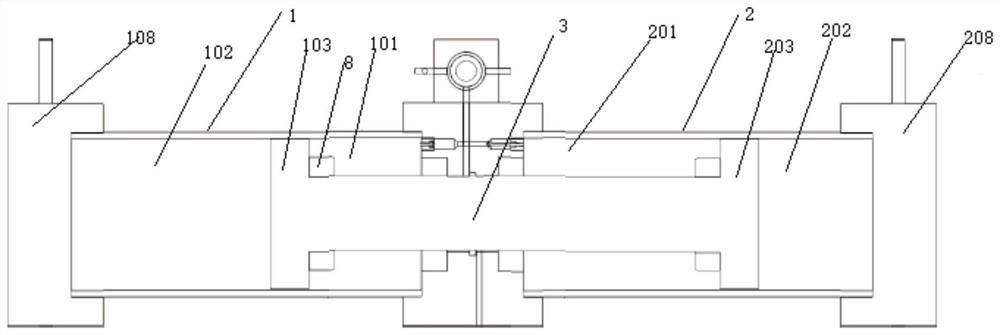
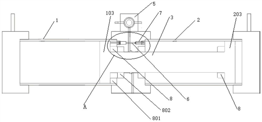
[0040]Such as Figure 1-3 , Image 6 with Figure 10 As shown, a hydraulically controlled self-reversing gas pressurized c...


PUM


Abstract

The invention discloses a hydraulically-controlled self-reversing gas pressurizing cylinder. The hydraulically-controlled self-reversing gas pressurizing cylinder is used in a gas compressor, a low-pressure hydraulic cavity is divided into two parts by buffering sleeves at the tail end of the stroke, one part discharges oil outwards through a throttling opening of an adjustable needle valve, hydraulic oil is provided for a control valve cavity of a hydraulically-controlled reversing valve through an internal flow channel, the automatic reversing action of the gas pressurizing cylinder is completed, the size of the throttling opening of the needle valve is adjusted, and the buffer effect of the inertia load of the pressurizing cylinder can be adjusted; and the other part is used for communicating a high-pressure hydraulic cavity and the low-pressure hydraulic cavity of the pressurizing cylinder at the tail end of the pressurizing stroke so as to realize self-pressure relief of a hydraulic system at the tail end of the stroke of the pressurizing cylinder. According to the hydraulically-controlled self-reversing gas pressurizing cylinder, self-reversing at the tail end of the stroke of the pressurizing cylinder and effective buffering of the inertia load of the pressurizing cylinder can be achieved at the same time, the gas pressurizing cylinder has the obvious effects of reducinghydraulic reversing impact and reducing inertia load impact, the service life of the gas pressurizing cylinder can be effectively prolonged, overall operation vibration and noises of the hydraulic compressor are reduced, and the gas pressurizing cylinder has the relatively-high engineering practical application value.

Description

technical field [0001] The invention relates to the field of petroleum equipment. More specifically, the present invention relates to a hydraulically controlled self-switching gas pressurized cylinder. Background technique [0002] Gas pressurization is widely used in the field of gas transportation, and the compressor is the key equipment for gas booster transportation. Hydraulic compressors have been widely used in natural gas refueling sub-stations because of their wide pressure range and relatively low cost. The gas booster cylinder is the core equipment of the hydraulic compressor. [0003] As people's awareness of safety and environmental protection gradually increases, hydraulic compressors must first meet the explosion-proof characteristics. At the same time, the vibration and noise of hydraulic compressors have gradually become important indicators to measure the overall performance of compressors. Existing hydraulic compressors generally use explosion-proof elec...

Claims


Application Information

Patent Timeline
Patent Type & Authority Applications(China)
IPC IPC(8): F15B3/00F15B13/02F15B15/17F15B15/14F15B15/22
CPCF15B3/00F15B13/02F15B15/17F15B15/1457F15B15/1428F15B15/1423F15B15/22
Inventor 高海平李红李新年宋满华吴刚
Owner CHINA PETROCHEMICAL CORP
Learn More