
Oil way circulation structure of brake

A cycle structure and brake technology, applied in the direction of brake type, brake actuator, axial brake, etc., can solve the problem of high oil temperature of gear oil, and achieve the effect of avoiding sealing effect and service life

Pending Publication Date: 2021-01-05
ZHEJIANG HAIHONG HYDRAULIC TECH
View PDF1 Cites 0 Cited by
  • Summary
  • Abstract
  • Description
  • Claims
  • Application Information

AI Technical Summary

Problems solved by technology

[0005] The object of the present invention is to solve the above-mentioned problems in the existing technology, and propose a brake oil circuit circulation structure. The technical problem to be solved by the present invention is: how to solve the problem of the gear oil oil temperature used to cool the dynamic friction plate and the static friction plate. too high problem

Method used


Image

  • Oil way circulation structure of brake
  • Oil way circulation structure of brake

Examples


Embodiment Construction

[0025] The following are specific embodiments of the present invention and in conjunction with the accompanying drawings, the technical solutions of the present invention are further described, but the present invention is not limited to these embodiments.

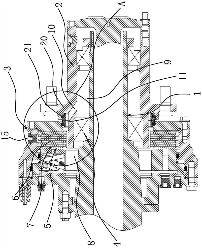
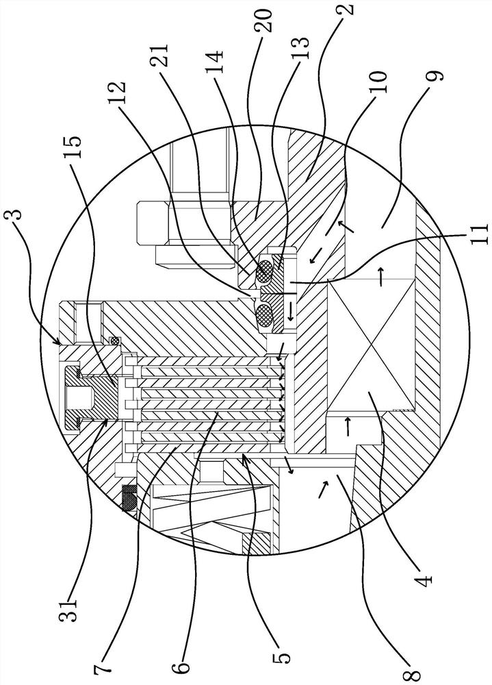
[0026] Such as figure 1 and figure 2 As shown, the oil circuit circulation structure of this brake, the brake includes a shaft head 1, a hub 2 sleeved on the shaft head 1 and a cylinder body 3 sleeved at the front end of the hub 2, and the bearing 4 passes between the shaft head 1 and the hub 2 connection, the cylinder body 3 has an installation cavity 5, and the installation cavity 5 has a brake disc 7 arranged on the cylinder body 3 and a friction disc 6 arranged on the hub 2, and the friction disc 6 is sleeved on the front end of the hub 2, and The friction plate 6 is connected to the wheel hub 2 through a spline; the brake plate 7 is connected to the cylinder body 3 through a spline, and there is a distance between t...


PUM


Abstract

The invention provides an oil way circulation structure of a brake, and belongs to the technical field of brakes. The oil way circulation structure solves the problem that the temperature of gear oilused for cooling a dynamic friction plate and a static friction plate of a brake in the prior art is too high. According to the oil way circulation structure of the brake, the brake comprises a shafthead, a hub arranged on the shaft head in a sleeving mode and a cylinder body arranged at the front end of the hub in a sleeving mode, the shaft head is connected with the hub through a bearing, a mounting cavity is formed in the cylinder body, and a brake pad arranged on the cylinder body and a friction plate arranged on the hub are arranged in the mounting cavity. The oil way circulation structure comprises a front oil cavity located in the front side of the bearing and a rear oil cavity located in the rear side of the bearing, the front oil cavity communicates with the rear oil cavity, andthe front oil cavity communicates with the mounting cavity. The oil way circulation structure further comprises an oil return hole located between the mounting cavity and the rear oil cavity, and theoil return hole is formed in the hub. The oil way circulation structure of the brake can prevent the situation that the sealing effect and the service life of a sealing piece are affected due to the fact that the temperature of the hydraulic oil in the mounting cavity is too high.

Description

technical field [0001] The invention belongs to the technical field of brakes, in particular to an oil circuit circulation structure of a brake. Background technique [0002] In the process of coal mining, rail cars are usually used to transport the coal in the mine to the outside of the mine. After the coal is stacked on the rail cars, the weight of the rail cars is very heavy. When the rail cars drive out of the mine, the rail cars need to be carried out Braking, because the rail car has a very large kinetic energy after running, generally a hydraulic brake is installed on the rail car to brake the rail car. [0003] For example, China Patent Network discloses a wet brake that prevents oil from leaking through holes [Application Publication No.: CN109707766A], which includes a hub, a brake housing, a hollow shaft head, a rotating piston, an elastic member, a dynamic friction plate, a static friction plate and an intermediate disc. The outer circumference of the hollow sha...

Claims


Application Information

Patent Timeline
IPC IPC(8): F16D55/24F16D65/16F16D121/04F16D125/02
CPCF16D55/24F16D65/16F16D2121/04F16D2125/02
Inventor 许甫高振家王星星赵林宾蔡一宇
Owner ZHEJIANG HAIHONG HYDRAULIC TECH
Learn More