
Shaft material drying device

A drying device and material technology, which is applied to the dryer of static materials, the arrangement of drying gas, and the drying of solid materials, can solve the problems of insufficient drying efficiency of crankshafts, improve processing cleanliness, improve drying efficiency, and avoid ground slippery effect

Active Publication Date: 2021-01-05
SAIC-GM-WULING AUTOMOBILE CO LTD
View PDF9 Cites 0 Cited by
  • Summary
  • Abstract
  • Description
  • Claims
  • Application Information

AI Technical Summary

Problems solved by technology

[0003] The main purpose of the present invention is to provide a drying device for shaft materials, aiming to solve the problems of insufficient drying of the crankshaft and low drying efficiency

Method used


Image

  • Shaft material drying device
  • Shaft material drying device

Examples


Embodiment Construction

[0024] The technical solutions in this embodiment will be clearly and completely described below in conjunction with the accompanying drawings in this embodiment. Obviously, the described embodiments are only part of the embodiments of the present invention, not all of them. Based on the embodiments of the present invention, all other embodiments obtained by persons of ordinary skill in the art without creative efforts fall within the protection scope of the present invention.

[0025] It should be noted that all directional indications (such as up, down, left, right, front, back...) in this embodiment are only used to explain the relative relationship between the various components in a certain posture (as shown in the figure). When the positional relationship, movement conditions, etc., if the specific posture changes, the directional indication will also change accordingly.

[0026] In addition, in the present invention, descriptions such as "first", "second" and so on are ...


PUM


Abstract

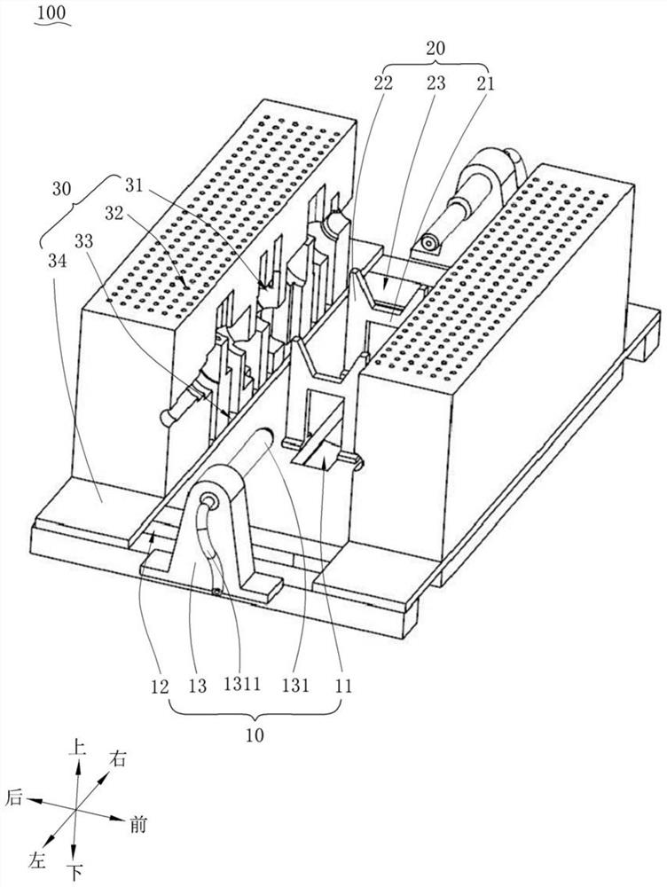
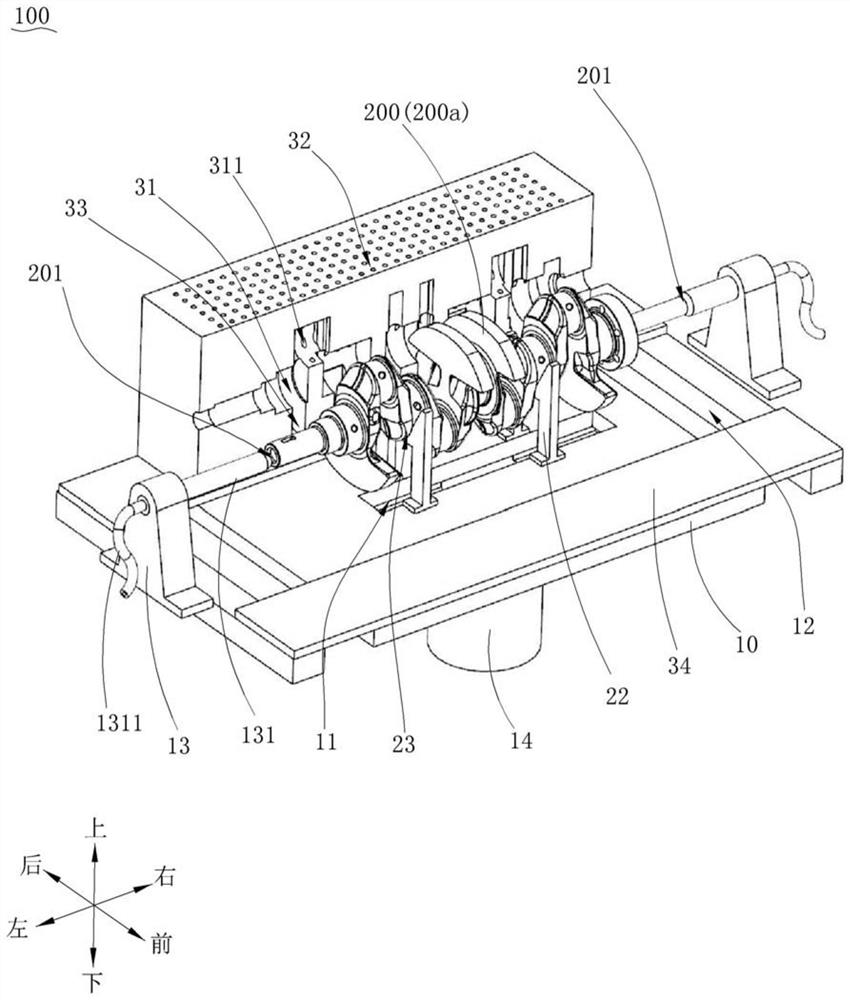
The invention discloses a shaft material drying device. The shaft material drying device comprises a base, a supporting frame and drying dies; a drainage groove is formed in the base; and the drainagegroove is communicated with an air draft piece through a pipeline. The supporting frame is mounted on the base, is arranged corresponding to the drainage groove and is used for supporting the shaft materials. The drying dies are arranged on the base in a sliding mode; drying cavities used for containing the shaft materials are formed in the drying dies; vent holes and drainage holes are correspondingly formed in the top walls and the bottom walls of the drying dies respectively; the vent holes and the drainage holes are communicated with the drying cavities; and the drying dies can slide relative to the base to envelop the shaft materials and enable the drainage holes to be communicated with the drainage groove. According to the shaft material drying device, the automatic and sufficient drying process of the shaft materials can be achieved; the machining quality is guaranteed; it is not required that an air gun is manually used for manually drying the shaft materials; the drying efficiency is improved; splashing of cutting fluid can be avoided; the machining cleanliness is improved; the eyes of an operator are protected against splashing of the cutting fluid; the situation that the cutting fluid splashes to the ground to cause slippery ground is avoided; and the shaft material drying device is safe and reliable.

Description

technical field [0001] The invention relates to the technical field of mechanical manufacturing, in particular to a shaft material drying device. Background technique [0002] During the processing of shaft materials, such as crankshafts, the crankshaft flows through the wet cutting station to the dry cutting station. After the crankshaft is processed by the wet cutting station, there is residual cutting fluid on the surface, which causes iron filings generated during the dry cutting of the crankshaft to adhere to the surface of the crankshaft, which affects the processing quality and cleanliness of the crankshaft, and the residual cutting fluid on the surface of the crankshaft Dropping onto the machine tool at the dry cutting station will also cause rusting of the machine tool components and reduce the service life of the equipment. The current solution is to manually blow dry the crankshaft with an air gun, which is inefficient and does not dry the crankshaft adequately. ...

Claims


Application Information

Patent Timeline
Patent Type & Authority Applications(China)
IPC IPC(8): F26B9/00F26B21/00F26B25/18F26B25/00
CPCF26B9/006F26B21/004F26B25/185F26B25/00
Inventor 吴明杰颜灿宝杨武
Owner SAIC-GM-WULING AUTOMOBILE CO LTD
Learn More