Deformed wing trailing edge design method based on knuckle type rigid-flexible coupling

A rigid-flexible coupling and design method technology, applied in the field of aerospace equipment, to ensure stable and reliable flight, meet the requirements of carrying capacity and stability, and overcome the effect of complex mechanisms

Active Publication Date: 2021-01-05
NORTHWESTERN POLYTECHNICAL UNIV
View PDF7 Cites 0 Cited by
  • Summary
  • Abstract
  • Description
  • Claims
  • Application Information

AI Technical Summary

Problems solved by technology

[0006] The technical problem to be solved by the present invention is: in order to avoid the defects of single flexible mechanism or rigid mechanism flexible wing in practical application, the present invention proposes a design method of deformable wing trailing edge based on "knuckle type" rigid-flexible coupling

Method used


Image

  • Deformed wing trailing edge design method based on knuckle type rigid-flexible coupling
  • Deformed wing trailing edge design method based on knuckle type rigid-flexible coupling
  • Deformed wing trailing edge design method based on knuckle type rigid-flexible coupling

Examples


Embodiment Construction

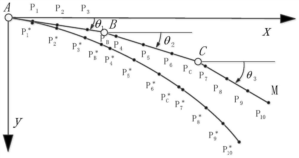
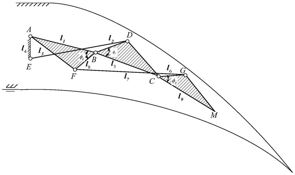
[0052] see figure 1 — Figure 8 , a design method for deformable wing trailing edge based on "knuckle-style" rigid-flexible coupling. Include the following steps:

[0053] Step 1: Genetic algorithm optimization of open-chain three-knuckle mechanism

[0054] a. The rigid mechanism at the trailing edge of the wing is a Watt-type six-bar mechanism, and its theoretical model is as follows image 3 As shown in the figure, the AB rod, BC rod, and CM rod are open-chain three-knuckle mechanisms. The degree of freedom of the open-chain three-bar mechanism is not 1, and the movement is uncertain. Therefore, it is necessary to pass through the AE rod, ED rod, and FG rod. The three links of the open chain are closed, and the degree of freedom of the whole set of rigid mechanisms is 1 after closing, which can ensure the deformation angle of the wing. The theoretical model of the driving mechanism is as Figure 7 As shown, the driving trailing edge mechanism adopts the slider crank mec...


PUM


Abstract

The invention relates to a deformed wing trailing edge design method based on knuckle type rigid-flexible coupling. The method comprises the following steps: optimizing a trailing edge rigid mechanismthrough a genetic algorithm according to a middle arc line of a wing section before and after trailing edge deformation; designing a trailing edge flexible mechanism through topological optimization;and finally, in order to facilitate machining and assembling, the flexible mechanism is simplified into a rigid rod and flexible hinge form, and a driving mechanism of the trailing edge is designed.The method is based on the rigid-flexible coupling design idea, the requirements for bearing capacity and stability can be met while large deformation of the trailing edge of the wing is achieved, andstable and reliable flight of an airplane is guaranteed.

Description

technical field [0001] The invention belongs to the technical field of aerospace equipment, and in particular relates to a design method for deformed wing trailing edge based on "knuckle-type" rigid-flexible coupling. Background technique [0002] Changes in flight conditions can be fully compensated by changing the chordwise camber of the wing during flight to obtain the optimal geometry for specific flight conditions. Such a wing is called a variable camber adaptive wing. This kind of variable camber adaptive wing based on medium-scale deformation has high aerodynamic efficiency, which can effectively improve the lift-to-drag ratio of the aircraft, reduce fuel consumption, and improve roll controllability. [0003] In 2001, Hans Peter Monner of the German Aerospace Center (DLR) published his design for a flexible flap system used in civil transport aircraft. The ribs are composed of hinges to achieve smooth bending without any additional gaps. Furthermore, the profile can...

Claims


Application Information

Patent Timeline
IPC IPC(8): G06F30/15G06F30/28G06N3/12G06F113/08G06F119/14
CPCG06F30/15G06F30/28G06N3/126G06F2113/08G06F2119/14
Inventor 葛文杰王君楠张永红朱旭耀王二亮
Owner NORTHWESTERN POLYTECHNICAL UNIV
Why Eureka
Try Eureka