Anti-collision induction device for profile laser cutting and control method thereof

A laser cutting and sensing device technology, applied in laser welding equipment, manufacturing tools, welding equipment, etc., can solve the problems of damage to the laser cutting head, laser cutting impact, etc., and achieve the effect of easy disassembly and damage prevention

Pending Publication Date: 2021-01-08
徐东新
View PDF7 Cites 4 Cited by
  • Summary
  • Abstract
  • Description
  • Claims
  • Application Information

AI Technical Summary

Problems solved by technology

[0004] The present invention proposes an anti-collision sensing device for profile laser cutting and its control method, which is used to solve the problem that when the existing profile laser cutting equipment in the background techn

Method used


Image

  • Anti-collision induction device for profile laser cutting and control method thereof
  • Anti-collision induction device for profile laser cutting and control method thereof
  • Anti-collision induction device for profile laser cutting and control method thereof

Examples


Example Embodiment

[0028]In the description of the present invention, it should be understood that the terms "upper", "lower", "front", "rear", "left", "right", "top", "bottom", "inner", " The orientation or positional relationship indicated by “outside” is based on the orientation or positional relationship shown in the drawings, and is only for the convenience of describing the present invention and simplifying the description, and does not indicate or imply that the device or element referred to must have a specific orientation to The specific azimuth structure and operation cannot be understood as a limitation of the present invention.

[0029]The technical solutions in the embodiments of the present invention will be clearly and completely described below in conjunction with the accompanying drawings in the embodiments of the present invention. Obviously, the described embodiments are only a part of the embodiments of the present invention, rather than all the embodiments.

[0030]ReferenceFigure 1-6As...


PUM


Abstract

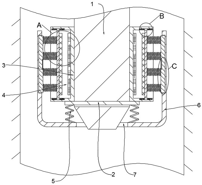
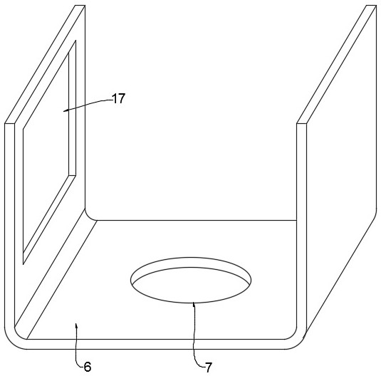
The invention discloses an anti-collision induction device for profile laser cutting. The anti-collision induction device comprises a laser cutting head body. A control method of the anti-collision induction device for profile laser cutting comprises a step of separately inserting two rectangular clamping blocks into two rectangular clamping grooves in a U-shaped protection plate. According to theanti-collision induction device for profile laser cutting and the control method thereof, the rectangular clamping blocks are inserted into the rectangular clamping grooves in the U-shaped protectionplate, so that elastic pieces are in contact with an annular block in an abutting manner. In addition, the laser cutting head body penetrates through a circular through groove in the U-shaped protection plate, so that the position of the U-shaped protection plate is effectively limited, and the dismounting and mounting are convenient. The U-shaped protection plate cooperates with the stainless steel elastic pieces to protect the lower end of the laser cutting head body, and first pressure springs and second pressure springs cooperate with first permanent magnet blocks and second permanent magnet blocks of the same magnetism to provide buffer protection to the laser cutting head body. Therefore, the impact on the cutting effect due to the contact between the U-shaped protection plate and profiles is avoided, and the damage to the laser cutting head body is prevented.

Description

technical field [0001] The invention relates to the technical field of profile laser cutting, in particular to an anti-collision sensing device for profile laser cutting and a control method thereof. Background technique [0002] Profile laser cutting is to irradiate the workpiece with a focused high-power-density laser beam, so that the irradiated material is rapidly melted, vaporized or reached the ignition point, and at the same time, the molten material is blown away by the high-speed airflow coaxial with the beam, so as to realize the thermal cutting of the workpiece. , Divided into four categories: laser vaporization cutting, laser melting cutting, laser oxygen cutting and laser scribing and controlled fracture. Laser cutting is characterized by non-contact cutting, which has the advantages of good cutting quality, high efficiency and fast speed. [0003] When the existing profile laser cutting equipment is actually used, the laser cutting head will inevitably touch th...

Claims


Application Information

Patent Timeline
IPC IPC(8): B23K26/38B23K26/70
CPCB23K26/38B23K26/702
Inventor 徐东新
Owner 徐东新
Why Eureka
Try Eureka