Wood stick punching equipment for furniture production

A kind of punching equipment and wooden stick technology, which is applied in the direction of fixed drilling machines, etc., can solve the problems of uneven punching of wooden sticks, hot sawdust, and people's injuries, so as to avoid burnt sawdust, improve quality and safety, and fast fix Effect

Inactive Publication Date: 2021-01-08
吴小冬
View PDF10 Cites 3 Cited by
  • Summary
  • Abstract
  • Description
  • Claims
  • Application Information

AI Technical Summary

Problems solved by technology

[0006] The present invention overcomes the disadvantages that when people punch wooden sticks with hand-held electric drills, manual operation errors easily lead to uneven drilling of wooden sticks, and the sawdust drilled by electric drills is hot and easily injures people. The technical problem is to provide a wooden stick punching equipment for furniture production which is safer for people to operate and more evenly punches sticks

Method used


Image

  • Wood stick punching equipment for furniture production
  • Wood stick punching equipment for furniture production
  • Wood stick punching equipment for furniture production

Examples


Embodiment 1

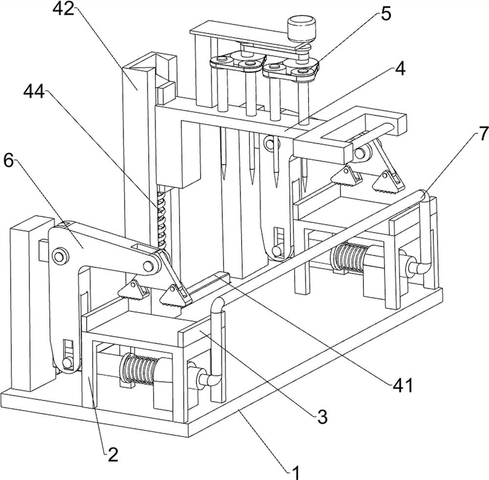
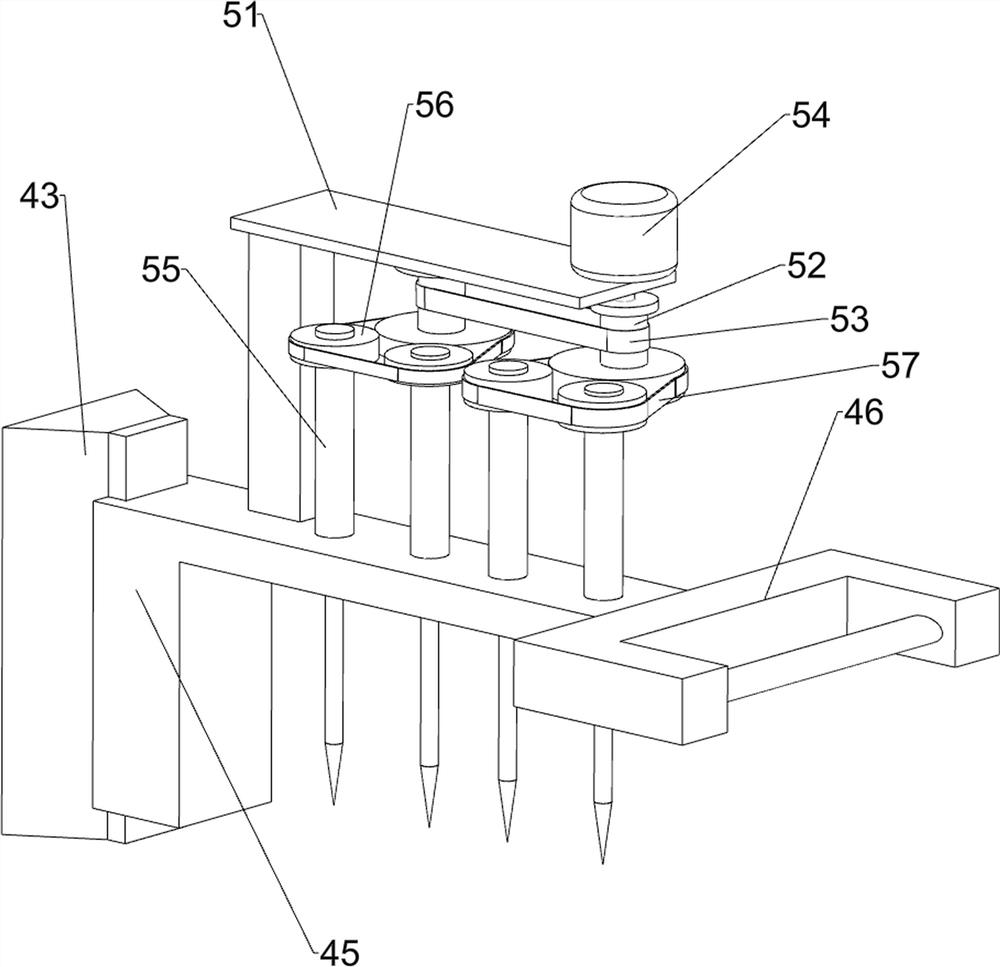
[0021] A wooden stick punching equipment for furniture production, such as figure 1 and figure 2 As shown, it includes a base plate 1, a placement frame 2, a baffle plate 3, a sliding mechanism 4 and a punching mechanism 5, the front and rear sides of the top of the base plate 1 are connected with the placement frame 2, and the left and right sides of the top of the placement frame 2 are connected with The left side of the baffle plate 3 and the top of the bottom plate 1 is slidably connected with a sliding mechanism 4 , and the right side of the upper part of the sliding mechanism 4 is connected with a punching mechanism 5 .

[0022] Sliding mechanism 4 comprises horizontal slide rail 41, vertical slide rail 42, slide block 43, support spring 44, first mounting bracket 45 and handle 46, and the left side of bottom plate 1 top is connected with horizontal slide rail 41, and the left side of horizontal slide rail 41 The upper part is slidably connected with a vertical slide r...

Embodiment 2

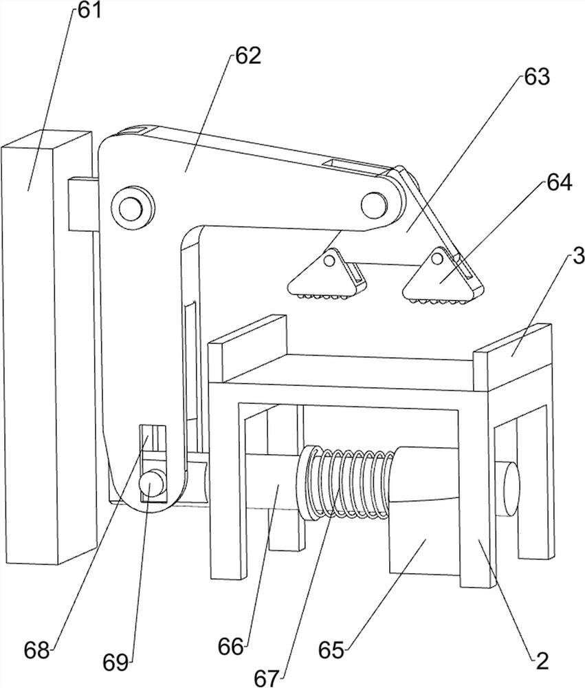
[0026] On the basis of Example 1, such as figure 1 and image 3 As shown, a clamping mechanism 6 is also included, and the clamping mechanism 6 includes a support column 61, an L-shaped swing arm 62, a clamping arm 63, a clamping block 64, a guide sleeve 65, a slide bar 66, a compression spring 67 and Positioning columns 69, the front and rear ends of the top left side of the base plate 1 are connected with supporting columns 61, the front sides of the two supporting columns 61 tops are hingedly connected with L-shaped swing arms 62, and the front sides of the two L-shaped swing arms 62 are connected to each other. Clamping arms 63 are hingedly connected, the bottoms of the two L-shaped swing arms 62 are provided with through grooves 68, the left and right sides of the clamping arms 63 bottoms are hingedly connected with clamping blocks 64, and the front and rear sides on the right side of the top of the base plate 1 Both ends are connected with guide sleeves 65, and the uppe...


PUM


Abstract

The invention relates to wood stick punching equipment, and in particular relates to wood stick punching equipment for furniture production. The technical problem to be solved by the invention is to provide the wooden stick punching equipment for furniture production, which is safer to operate by people and more uniform in punching of wooden sticks. In order to solve the technical problem, the invention provides the wood stick punching equipment for furniture production that comprises at least two placing frames, connected to a base plate; at least two baffles, connected to the placing frames;a sliding mechanism, connected to one side of the bottom plate in a sliding manner; and a punching mechanism, connected to the sliding mechanism. Under the action of the sliding mechanism and the punching mechanism, a wood stick can be rapidly and uniformly punched, and the people are prevented from being scalded by high-temperature wood chips.

Description

technical field [0001] The invention relates to a stick punching device, in particular to a stick punching device for furniture production. Background technique [0002] Sticks need to be crafted on the crafting bar or workbench. Two sticks can be used to synthesize pickaxes, swords, hoes, shovels, and axes of various materials. Sticks can also be used as fuel in furnaces, and sticks can also be used in furniture production. When people use wooden sticks to make furniture, existing wooden sticks need to be processed. [0003] At present, when people process and punch wooden sticks for furniture, they generally fix the wooden sticks first, and then punch the wooden sticks one by one with a hand-held electric drill. In this way, due to the high temperature of the sawdust drilled by the electric drill, It is easy to cause certain injuries to people, and it is relatively unsafe, and due to the error of manual operation, it is easy to cause uneven perforation of the stick, resu...

Claims


Application Information

Patent Timeline
Patent Type & Authority Applications(China)
IPC IPC(8): B27C3/04
CPCB27C3/04
Inventor 吴小冬
Owner 吴小冬
Why Eureka
Try Eureka