Hybrid drive system and vehicle

A drive system and hybrid technology, applied in hybrid vehicles, motor vehicles, power units, etc., can solve the problems of large size and high cost, and achieve the effects of improving driving stability, facilitating speed regulation, and improving fuel economy.

Active Publication Date: 2022-03-18
BYD CO LTD +1
View PDF0 Cites 0 Cited by
  • Summary
  • Abstract
  • Description
  • Claims
  • Application Information

AI Technical Summary

Problems solved by technology

[0008] The technical problem to be solved in this application is: aiming at the technical problems of high cost and large volume existing in the existing dual-motor or dual-clutch hybrid drive system with the functions of uninterrupted power output during the shifting process and power generation during parking, provide A hybrid drive system and vehicle with single motor, single clutch and uninterrupted output power

Method used


Image

  • Hybrid drive system and vehicle
  • Hybrid drive system and vehicle
  • Hybrid drive system and vehicle

Examples


no. 1 example

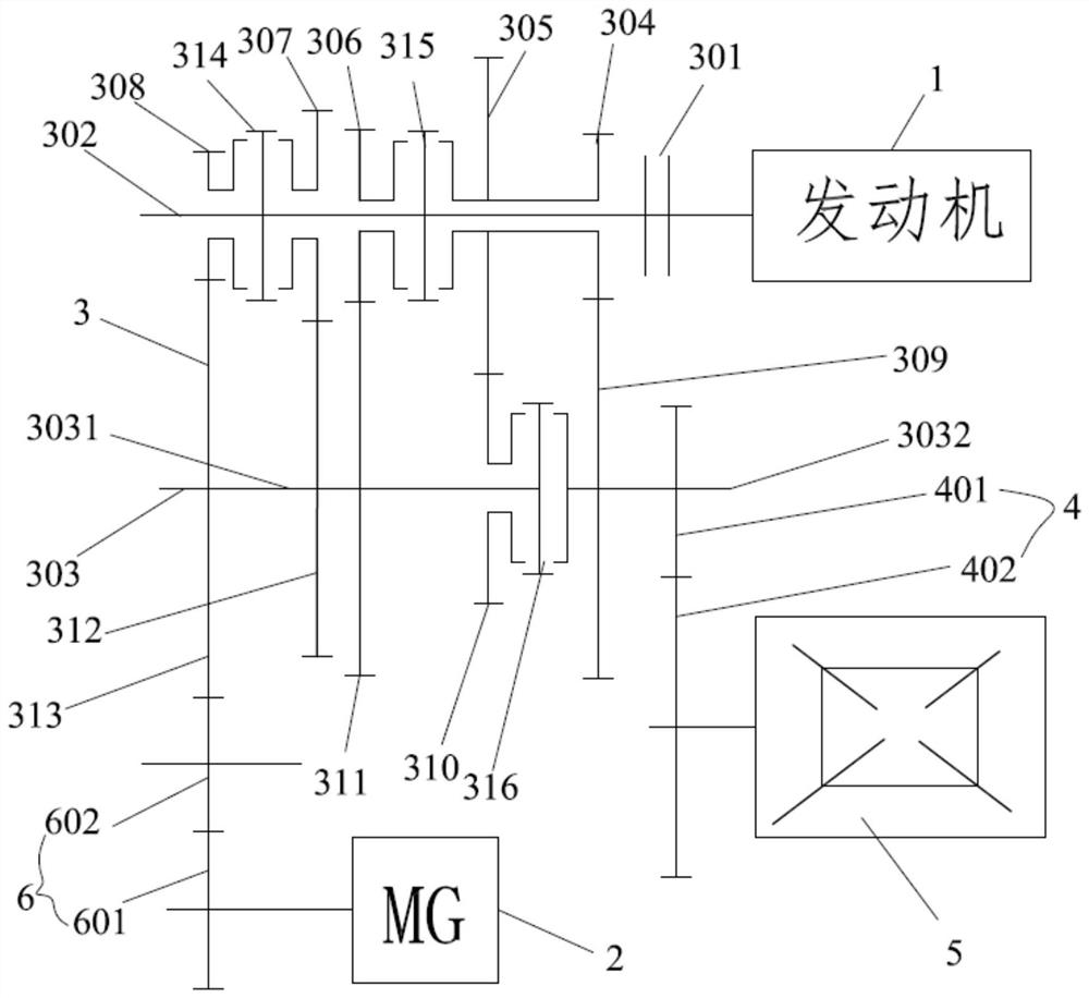
[0081] Such as figure 1 As shown, the hybrid drive system 100 provided by the first embodiment of the present application includes an engine 1 , a gearbox and a motor 2 , and the gearbox includes a speed change mechanism 3 and a final reducer 4 .

[0082] The speed change mechanism 3 includes a clutch device 301, an input shaft 302, an output shaft 303, a synchronizing device, a plurality of driving gears arranged on the input shaft 302 and a plurality of driving gears arranged on the output shaft 303 and a plurality of the driving gears arranged on the output shaft 303. The gears correspond to a plurality of driven gears, and the clutch device 301 is connected between the engine 1 and the input shaft 302 . The motor 2 is connected to the output shaft 303 through a reduction gear set 6, and the output shaft 303 is connected to the final reducer 4 to output power.

[0083] The output shaft 303 is disconnected in the middle into a first output shaft 3031 and a second output sha...

no. 2 example

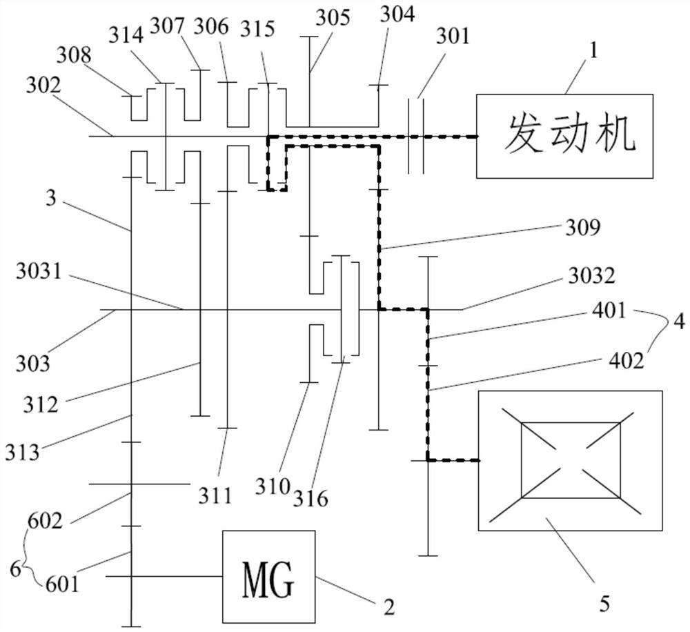
[0119] Figure 22 A hybrid drive system 100 of a second embodiment of the present application is shown. It differs from the first embodiment as follows:

[0120] In the second embodiment, the plurality of driving gears include a first driving gear 304 , a second driving gear 305 , a third driving gear 306 , The fourth driving gear 307 and the fifth driving gear 308; the plurality of driven gears include a first driven gear 309, a second driven gear 310, a third driven gear arranged in sequence in a direction away from the engine 1 Gear 311, the fourth driven gear 312 and the fifth driven gear 313, the first driven gear 309 and the second driven gear 310 are fixed on the second output shaft 3032, the third driven gear 311 is loosely sleeved on the first output shaft 3031 , and the fourth driven gear 312 and the fifth driven gear 313 are fixed on the first output shaft 3031 . The first driving gear 304 meshes with the first driven gear 309, the second driving gear 305 meshes ...

no. 3 example

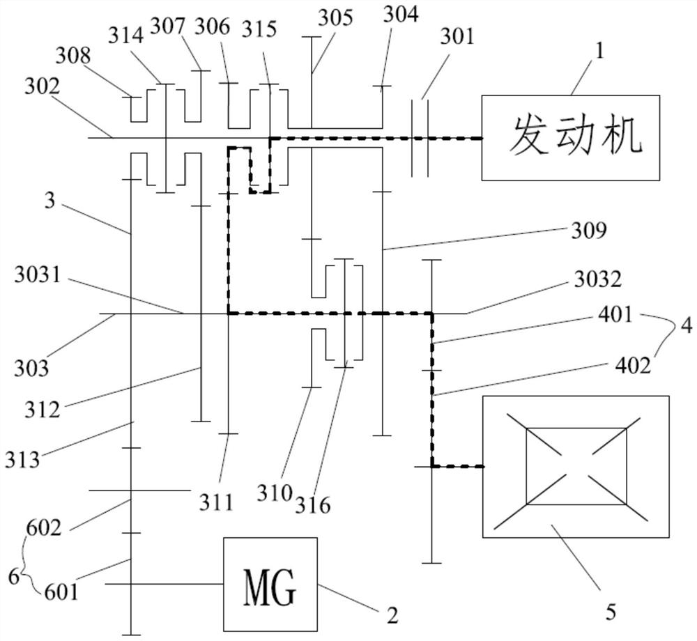
[0124] Figure 23 A hybrid drive system 100 of a third embodiment of the present application is shown. It differs from the first embodiment as follows:

[0125] The motor 2 is connected to the input shaft 302 through the reduction gear set 6 . The intermediate gear 602 meshes with the fifth driving gear 308 .


PUM


Abstract

This application belongs to the field of hybrid technology, and relates to a hybrid drive system and a vehicle. The hybrid drive system includes an engine, a gearbox and a motor, and the gearbox includes a speed change mechanism and a final drive; For the first output shaft and the second output shaft, the synchronization device is composed of a plurality of synchronizers, one of which is set at the disconnected position of the output shaft and connects or disconnects the first output shaft And the second output shaft is used to control the power combination and power disconnection of the first output shaft and the second output shaft, so as to realize multiple different power transmission paths. Since the disconnected position of the output shaft is provided with a synchronizer that connects the first output shaft and the second output shaft and is used to control the power combination and power disconnection of the first output shaft and the second output shaft, the hybrid drive system can use less The synchronizer realizes multiple gears, and the axial dimension is short, so the requirement for the axial dimension of the motor is not high.

Description

technical field [0001] The present application belongs to the technical field of hybrid power, and in particular relates to a hybrid power drive system and a vehicle. Background technique [0002] The development and utilization of new energy vehicles has gradually become a trend. As one of the new energy vehicles, a hybrid vehicle is driven by an engine and / or an electric motor, and has multiple modes, which can improve transmission efficiency and fuel economy. [0003] An existing hybrid drive system includes an engine, a drive motor, a dual-clutch transmission and a power battery, etc., wherein the output shaft of the engine is connected to a dual-clutch transmission, and the output shaft of the drive motor is fixedly connected with a gear meshing with the final drive. gears to output power. [0004] Since the drive motor is directly connected to the gear of the main reducer through gears, the hybrid power drive system cannot realize parking power generation. Moreover,...

Claims


Application Information

Patent Timeline
Patent Type & Authority Patents(China)
IPC IPC(8): B60K6/36B60K6/543B60L50/61
CPCB60K6/36B60K6/543B60L50/61Y02T10/62Y02T10/70
Inventor 费学安刘华朝华煜储昭伟潘世翼
Owner BYD CO LTD
Why Eureka
Try Eureka