
Multistage micro-power self-reflux sewage treatment reactor

A sewage treatment and reactor technology, applied in the field of water treatment, can solve the problems of large floor area, increased power consumption, high construction investment, etc., achieve floor space saving, efficient denitrification and phosphorus removal, reduce construction cost and The effect of running costs

Pending Publication Date: 2021-01-08
辽宁一诺环境产业集团有限公司
View PDF0 Cites 0 Cited by
  • Summary
  • Abstract
  • Description
  • Claims
  • Application Information

AI Technical Summary

Problems solved by technology

However, the disadvantage of this process is that the return mixed liquid and sludge need to be equipped with power equipment such as a return pump, and the power consumption will be increased. It is also necessary to set up power equipment such as mixers and flow devices, which also increases power consumption.
In addition, the existing solid-liquid separation and clarification zone is in A 2 The / O reactor is independently installed outside the container, which occupies a large area and requires high construction investment

Method used


Image

  • Multistage micro-power self-reflux sewage treatment reactor
  • Multistage micro-power self-reflux sewage treatment reactor
  • Multistage micro-power self-reflux sewage treatment reactor

Examples


Embodiment Construction

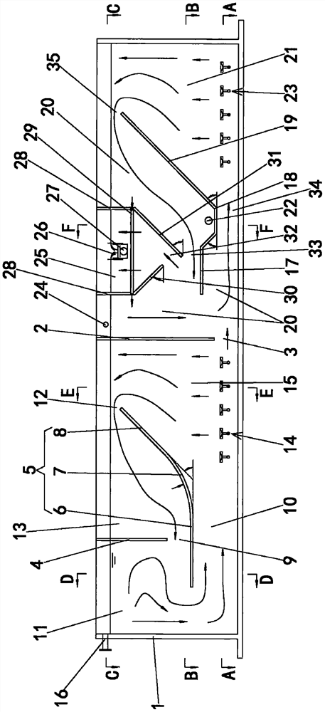
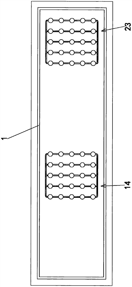
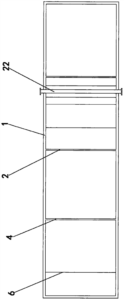
[0033] Such as Figure 1 to Figure 7As shown, the microdynamic self-reflux sewage treatment reactor of the present invention includes a hollow reactor body 1, and the reactor body 1 of this embodiment is in the shape of a cuboid. The reactor body 1 divides the inner cavity into two parts, the primary reaction zone and the secondary reaction zone, through the partition plate 2 arranged on the upper wall of the interior cavity. The partition plate 2 of this embodiment is vertically connected to the interior of the reactor body 1 chamber wall. A first water passage 3 is formed between the lower end of the partition plate 2 and the reactor body 1 . The primary reaction zone is provided with a primary hydraulic circulation structure, and the secondary reaction zone is provided with a secondary hydraulic circulation structure.

[0034] The primary hydraulic circulation structure includes a first deflector 4 vertically arranged on the upper wall of the primary reaction zone and a s...


PUM

PropertyMeasurementUnit
angleaaaaaaaaaa
radiusaaaaaaaaaa

Abstract

The invention discloses a micro-power self-reflux sewage treatment reactor which comprises a reactor body, an inner cavity of the reactor body is divided into a first-stage reaction zone and a second-stage reaction zone through a partition plate, a first water passing channel is formed between the lower end of the partition plate and the reactor body, and a first-stage hydraulic circulation structure and a second-stage hydraulic circulation structure are arranged in the first-stage reaction zone and the second-stage reaction zone. A first power assembly is arranged between the right portion, below the first-stage hydraulic circulation structure, of the lower surface of the first-stage reaction area and the partition plate, and a second power assembly is arranged between the right portion,below the second-stage hydraulic circulation structure, of the lower surface of the second-stage reaction area and the right side plate of the reactor body; the left side wall of the reactor body is provided with a water inlet a segmented water inlet is formed in the second-stage reaction zone on the reactor body, a solid-liquid separation clarification zone is arranged above the second-stage water circulation structure, a water collecting tank and a water passing weir are arranged in the solid-liquid separation clarification zone, and the water collecting tank and the water passing weir are communicated with the outside of the reactor body through a water outlet pipe. The reactor is energy-saving, reduces the equipment capacity, simplifies the operation, and saves the occupied area, equipment cost and operating cost.

Description

technical field [0001] The invention relates to the technical field of water treatment, in particular to a multi-stage micro-dynamic self-reflux sewage treatment reactor for treating sewage and waste water. Background technique [0002] A 2 The / O method is the abbreviation of the Anaerobic / Anoxic / Oxic process. In the method, an anaerobic biological treatment process is added before the conventional anoxic / aerobic biological treatment system, so as to achieve the effect of removing nitrogen and phosphorus while removing organic pollutants. The role of the anaerobic biochemical stage is a biological selector. Phosphorus accumulating bacteria release phosphorus to obtain energy under anaerobic conditions, creating conditions for aerobic phosphorus uptake; in the aerobic biochemical stage, microorganisms oxidize and decompose sewage and wastewater under the condition of sufficient dissolved oxygen Nitrification and phosphorus accumulation reactions are carried out at the same...

Claims


Application Information

Patent Timeline
Patent Type & Authority Applications(China)
IPC IPC(8): C02F3/30C02F101/10C02F101/16
CPCC02F3/301C02F3/302C02F3/308C02F2101/105C02F2101/16C02F2301/08
Inventor 秦明峰徐道胜亢中举李永健田璐
Owner 辽宁一诺环境产业集团有限公司
Learn More