
Light blocking prevention type solar lawn lamp

A technology of lawn lamps and solar energy, applied in electric light sources, photovoltaic modules, photovoltaic power generation, etc., can solve the problems of unable to clean lamps and reduce the light energy absorption efficiency of solar panels, so as to reduce the temperature, improve the landscape effect and prolong the use The effect of longevity

Pending Publication Date: 2021-01-08
王秀兰
View PDF9 Cites 0 Cited by
  • Summary
  • Abstract
  • Description
  • Claims
  • Application Information

AI Technical Summary

Problems solved by technology

[0003] Since lawn lamps are often not very high and are set outdoors, when the wind blows, it is inevitable that grass leaves or other debris on the ground will be blown to the solar panels above the lamps and block the solar panels. , which greatly reduces the absorption efficiency of solar panels to light energy, and the staff cannot clean up the lamps in a long-term and timely manner.

Method used


Image

  • Light blocking prevention type solar lawn lamp
  • Light blocking prevention type solar lawn lamp
  • Light blocking prevention type solar lawn lamp

Examples


Embodiment 1

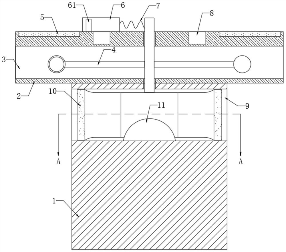
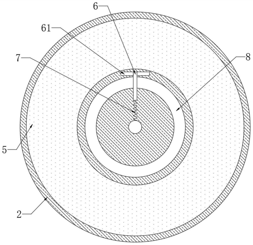
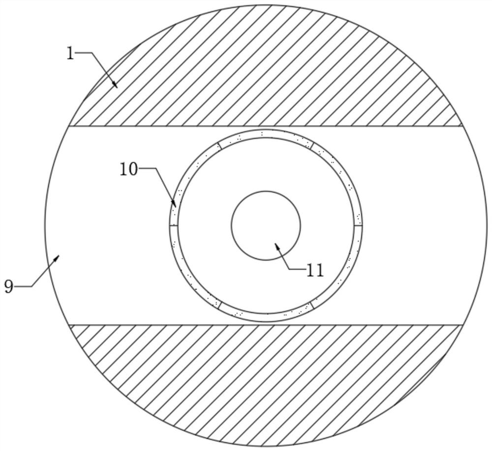
[0021] refer to Figure 1-3 , an anti-light-blocking solar lawn lamp, including a support column 1, the upper end of the support column 1 is provided with a light plate 2, the upper end of the light plate 2 is installed with a solar panel 5, specifically, the solar panel 5 is a ring structure, like figure 2 shown. The side wall of the light receiving plate 2 is provided with a ventilation groove 3, and the inner bottom of the ventilation groove 3 is rotatably connected with a wind wheel 4. It should be noted that the diameter of the wind wheel 4 is smaller than the groove width of the ventilation groove 3, so that the wind wheel 4 can be ventilated. The groove 3 circulates and rotates without being blocked by the inner wall of the ventilation groove 3. In addition, the blades of the wind wheel 4 are made into an air cup shape, which can ensure that the horizontally blowing airflow can smoothly push the wind wheel 4 to rotate. A scraper 6 is slidably connected to the upper e...

Embodiment 2

[0026] refer to Figure 4 , Different from the first embodiment, the side wall of the support column 1 is provided with a through hole 12, and the inner bottom of the through hole 12 is provided with an elastic air film 13. Specifically, the elastic air film 13 is made of rubber material and has good self-recovery ability. , the side wall of the support column 1 is provided with a liquid storage tank 16, the liquid storage tank 16 is filled with cooling liquid, and a one-way liquid inlet pipe 15 and one-way liquid return pipe 14 are communicated between the liquid storage tank 16 and the elastic gas film 13. , the one-way liquid inlet pipe 15 only allows the cooling liquid to flow from the liquid storage tank 16 to the elastic gas film 13, and the one-way liquid return pipe 14 only allows the cooling liquid to flow from the elastic gas film 13 to the liquid storage tank 16. A one-way valve can be installed in the pipeline. A liquid injection port 161 is opened on the inner wal...


PUM


Abstract

The invention discloses a light blocking prevention type solar lawn lamp. The solar lawn lamp comprises a supporting column, wherein a light facing plate is arranged at the upper end of the supportingcolumn, a solar cell panel is installed at the upper end of the light facing plate, a ventilation groove is formed in the side wall of the light facing plate, a wind wheel is rotatably connected to the inner bottom of the ventilation groove, a scraping plate is slidably connected to the upper end of the light facing plate, the scraping plate is elastically connected to the side wall of a wind wheel rotating shaft through a spring, pull-back plates are fixedly connected to the two opposite side walls of the scraping plate correspondingly, and an annular groove is formed in the upper end of thelight facing plate. By arranging the wind wheel, the spring, the scraping plate and other components, the wind wheel can be pushed to rotate when wind blows, the scraping plate is pushed to the surface of the solar cell panel through centrifugal force, and therefore, grass leaves and other sundries falling on the surface of the solar cell panel are scraped together; and when the wind stops, the spring pulls the scraping plate to move back, the pull-back plates can push grass leaves and other sundries into the annular groove, and therefore, the grass leaves and other sundries can be effectively prevented from shielding the solar cell panel.

Description

technical field [0001] The invention relates to the technical field of lamps, in particular to a light-blocking solar lawn lamp. Background technique [0002] In order to improve the landscape effect of the park or community, an appropriate amount of lawn lights are often set on the lawn to bring out the landscape of the lawn. At present, solar lawn lights are more commonly used, which use solar panels to absorb light energy during the day and convert it into electrical energy for storage, and make lawn lights glow at night. [0003] Since lawn lights are often not very high and are set in the open outdoors, when the wind blows, grass leaves or other debris on the ground will inevitably be blown to the solar panels above the lamps and block the solar panels. , greatly reducing the absorption efficiency of solar panels to light energy, and the staff cannot clean the lamps in a long-term and timely manner. Accordingly, this application document proposes a light-blocking sola...

Claims


Application Information

Patent Timeline
Patent Type & Authority Applications(China)
IPC IPC(8): F21S9/03F21V29/56F21V29/83F21V29/67H02S40/10F21W131/10
CPCF21S9/035F21V29/56F21V29/83F21V29/67H02S40/10F21W2131/10Y02B20/72Y02E10/50
Inventor 王秀兰
Owner 王秀兰
Learn More