Porous medium liquid film small-channel cooling device

A technology of porous media and cooling device, which is applied in the direction of modification with liquid cooling, modification with cooling/ventilation/heating, modification with gaseous coolant, etc. It can solve the problem that the steam cannot be dissipated in time, affecting the cooling performance of equipment, and it is difficult to simultaneously Implementation and other issues to achieve the effect of shortening cooling time, decoupling connection and conflict, and efficient cooling performance

Active Publication Date: 2021-01-08
SHANGHAI MARITIME UNIVERSITY
View PDF17 Cites 2 Cited by
  • Summary
  • Abstract
  • Description
  • Claims
  • Application Information

AI Technical Summary

Problems solved by technology

In fact, it is difficult to achieve high permeability and large specific surface area at the same time.
At the same time, the steam generated on the surface of the porous structure cannot be dissipated in time, which will also affect the cooling performance of the equipment

Method used


Image

  • Porous medium liquid film small-channel cooling device
  • Porous medium liquid film small-channel cooling device
  • Porous medium liquid film small-channel cooling device

Examples


Embodiment 1

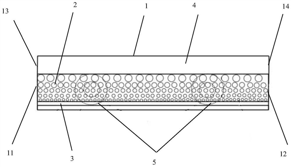
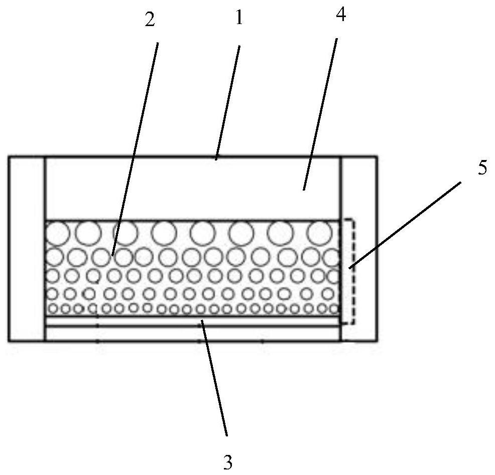
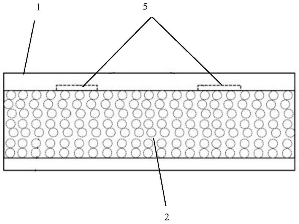
[0029] A porous medium liquid film small channel cooling device provided by an embodiment of the present invention, please refer to figure 1 , figure 2 and image 3 As shown, the channel cooling body 1 is included, and the channel cooling body 1 is a cuboid hollow structure. The channel cooling body 1 is provided with a porous structure 2 along the lateral direction. The porous structure 2 divides the channel cooling body 1 into upper and lower cavities. The porous structure Between the lower surface of the channel cooling body 1 and the inner bottom of the channel cooling body 1 is a flowing liquid film layer 3, between the upper surface of the porous structure 2 and the inner top of the channel cooling body 1 is an air evaporation channel 4, and the inner wall of the channel cooling body 1 is embedded An ultrasonic generator 5 is provided, and the ultrasonic generator 5 is located on one side of the porous structure 2. The ultrasonic waves emitted by the ultrasonic generat...

Embodiment 2

[0036] A porous medium liquid film small channel cooling device provided by an embodiment of the present invention, please refer to Figure 4 , Figure 5 and Figure 6As shown, the channel cooling body 1 is included, and the channel cooling body 1 is a cuboid hollow structure. The channel cooling body 1 is provided with a porous structure 2 along the lateral direction. The porous structure 2 divides the channel cooling body 1 into upper and lower cavities. The porous structure Between the lower surface of the channel cooling body 1 and the inner bottom of the channel cooling body 1 is a flowing liquid film layer 3, between the upper surface of the porous structure 2 and the inner top of the channel cooling body 1 is an air evaporation channel 4, and the inner wall of the channel cooling body 1 is embedded An ultrasonic generator 5 is provided, and the ultrasonic generator 5 is located on one side of the porous structure 2. One end of the channel cooling main body 1 is provide...


PUM


Abstract

The invention discloses a porous medium liquid film small-channel cooling device, and relates to the technical field of electronic equipment cooling. The porous medium liquid film small-channel cooling device comprises a channel cooling main body, wherein a porous structure is arranged in the channel cooling main body, a flowing liquid film layer is arranged between the lower surface of the porousstructure and the inner bottom of the channel cooling main body, an air evaporation channel is formed between the upper surface of the porous structure and the top in the channel cooling main body, an ultrasonic wave generator is embedded in the inner side wall of the channel cooling main body and located on one side of the porous structure, and the porosity of the porous structure is linearly orstepwise increased from bottom to top. According to the invention, by using a variable-pore porous structure, the permeability and the specific surface area of a flowing liquid film in the porous structure are improved in the heat production direction, so that the relation and conflict between flowing performance and heat transfer performance are effectively decoupled, the cooling performance ofthe cooling device is improved, the cooling time is shortened; micro-convection of liquid in pores of the porous structure is promoted under the action of cavitation and acoustic streaming of ultrasonic waves, and fluid disturbance is enhanced.

Description

technical field [0001] The invention relates to the technical field of small channel cooling devices, in particular to a porous medium liquid film small channel cooling device. Background technique [0002] At present, the high power and high heat flux characteristics of industrial equipment have made the safety and stability of equipment work increasingly prominent. The problem of heat dissipation and cooling in a small space has become the main bottleneck limiting the further improvement of equipment performance, so it is necessary to design a device with efficient cooling performance. Flowing liquid film evaporation has high heat transfer performance and is widely used in industrial fields such as electronic equipment cooling. In conventional channel cooling devices, a single-layer porous structure with constant porosity covered in a liquid film channel with flow is mostly adopted, resulting in lower cooling performance. In this traditional design, the conflict between ...

Claims


Application Information

Patent Timeline
Patent Type & Authority Applications(China)
IPC IPC(8): H05K7/20
CPCH05K7/20127H05K7/20209H05K7/20309H05K7/20327H05K7/20381
Inventor 刘燚陈威程前戴浩董学波白玉龙
Owner SHANGHAI MARITIME UNIVERSITY
Why Eureka
Try Eureka