
Remote control pneumatic control mechanism of single-row corn harvester

A corn harvester, pneumatic control technology, applied in harvesters, agricultural machinery and implements, applications, etc., can solve the problems of increasing the labor intensity of the operator, reducing the operator, and the operator being easily fatigued.

Pending Publication Date: 2021-01-12
山东沭丰农业装备有限公司
View PDF0 Cites 0 Cited by
  • Summary
  • Abstract
  • Description
  • Claims
  • Application Information

AI Technical Summary

Problems solved by technology

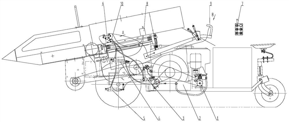
[0003] The purpose of the present invention is to provide a remote control pneumatic operating mechanism for a single-row corn harvester to solve the need for single-row corn harvesters in the prior art to use pull rods, pedals, etc. to directly manipulate the clutch, brake and other actions of the single-row corn harvester Larger force, due to the direct manipulation of manpower increases the labor intensity of the operator and makes the operator prone to fatigue, it effectively reduces the labor intensity of the operator, and the operator does not have to sit on the single-row corn harvester, and can walk and follow in the field The machine controls the single-row corn harvester through the remote control signal transmitter, which is convenient for observing the corn feeding situation of the header and improving the harvesting efficiency

Method used


Image

  • Remote control pneumatic control mechanism of single-row corn harvester
  • Remote control pneumatic control mechanism of single-row corn harvester
  • Remote control pneumatic control mechanism of single-row corn harvester

Examples


Embodiment Construction

[0028] In order to make the purpose, technical solution and advantages of the present invention clearer, the technical solution of the present invention will be described in detail below. Apparently, the described embodiments are only some of the embodiments of the present invention, but not all of them. Based on the embodiments of the present invention, all other implementations obtained by persons of ordinary skill in the art without making creative efforts fall within the protection scope of the present invention.

[0029] Hereinafter, the embodiments will be described in detail in conjunction with the accompanying drawings. In addition, the examples shown below do not limit the content of the invention described in the claims in any way. In addition, all the contents of the configurations shown in the following embodiments are not limited to be essential to the solution of the invention described in the claims.

[0030] Please refer to the attached Figure 1-3 , the sin...


PUM


Abstract

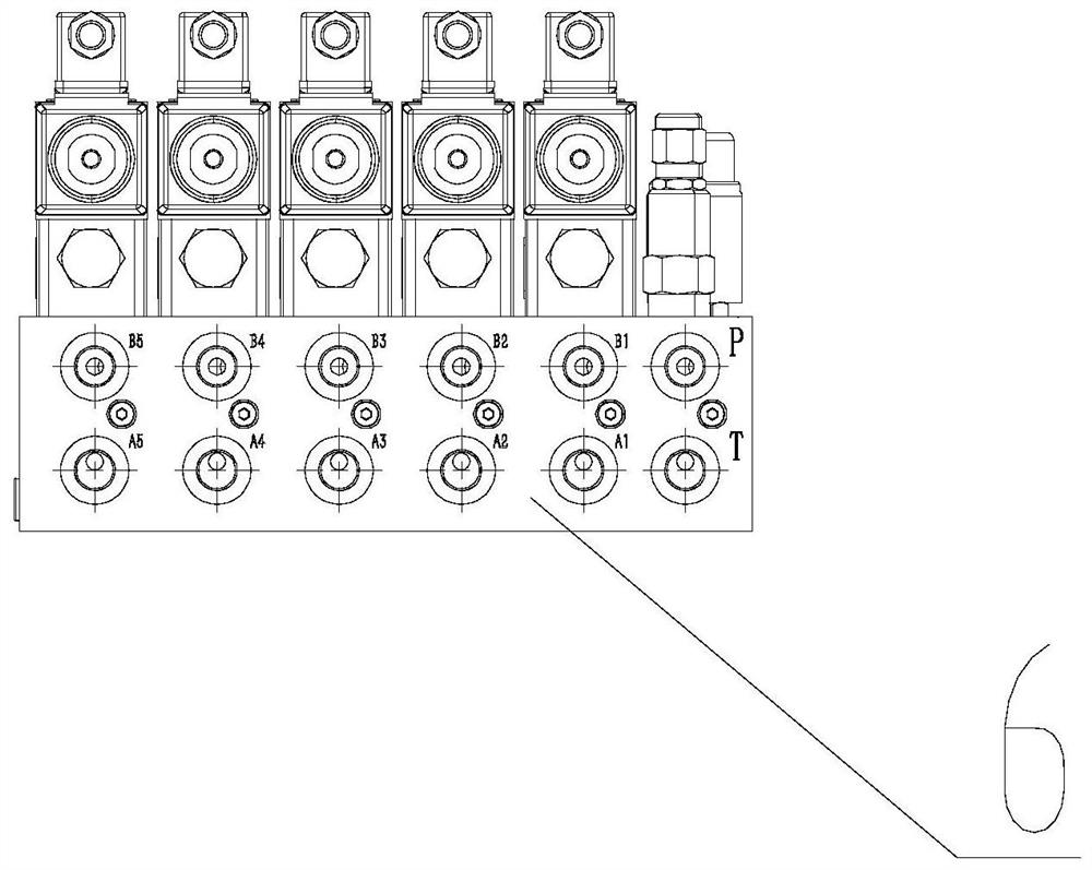
The invention discloses a remote control pneumatic control mechanism of a single-row corn harvester. The remote control pneumatic control mechanism comprises a steering air cylinder, a brake air cylinder, a clutch air cylinder, a valve device, an air supply device, a remote control signal transmitting device and a remote control signal receiving device. When the remote control signal transmittingdevice is operated, the remote control signal receiving device receives signals and controls the valve device to connect different air channels so that compressed air of the air supply device can drive the clutch air cylinder, the steering air cylinder and the brake air cylinder to act, and remote control clutch, steering and brake of the corn harvester are achieved. The problems that when an existing single-row corn harvester is used for harvesting, a pull rod, a pedal and the like are used for directly controlling clutching, braking and other actions, large force is needed, the labor intensity of an operator is increased, and the operator is prone to fatigue are solved; the labor intensity of the operator is effectively relieved, and the operator does not need to sit on the harvester andcan walk and follow in the field; and the single-row corn harvester is operated through the remote control signal transmitting device, the corn feeding condition of a header is convenient to observe,and the harvesting efficiency is improved.

Description

technical field [0001] The invention relates to the technical field of agricultural machinery, and more specifically relates to a remote control pneumatic operating mechanism for a single-row corn harvester. Background technique [0002] At present, the operating mechanisms of single-row corn harvesters developed on the market all adopt mechanical direct manipulation. This kind of mechanism is mainly realized by pull rods, pedals, etc. Although this kind of mechanism is simple and practical, it has certain defects: first, this kind of mechanism When using pull rods, pedals, etc. to directly manipulate the clutch and brake actions of the single-row corn harvester, it takes a lot of force. The direct manipulation of manpower increases the labor intensity of the operator and makes the operator prone to fatigue. Secondly, for some single-row corn harvesters, the operator needs to ride on the machine to operate continuously, which is not conducive to observing the corn feeding si...

Claims


Application Information

Patent Timeline
IPC IPC(8): A01D45/02A01D69/10A01D69/08A01D69/00
CPCA01D45/02A01D45/028A01D69/00A01D69/08A01D69/10
Inventor 王波景光法张波李军
Owner 山东沭丰农业装备有限公司
Learn More