Self-exhausting type safe injector

A safety syringe and self-exhausting technology, applied in the field of syringes, can solve problems such as affecting injection efficiency and complicated operation, and achieve the effect of improving safety

Inactive Publication Date: 2021-01-12
陆明京
View PDF0 Cites 0 Cited by
  • Summary
  • Abstract
  • Description
  • Claims
  • Application Information

AI Technical Summary

Problems solved by technology

[0004] The purpose of the present invention is to solve the disadvantages in the prior art that before using the syringe to inject the liquid medicine, the air in the syringe needs to be manually discharged, the operation is cumbersome, and the shortcomings of affecting the injection efficiency are proposed, and a self-venting safety syringe is proposed.

Method used


Image

  • Self-exhausting type safe injector
  • Self-exhausting type safe injector
  • Self-exhausting type safe injector

Examples


Embodiment 1

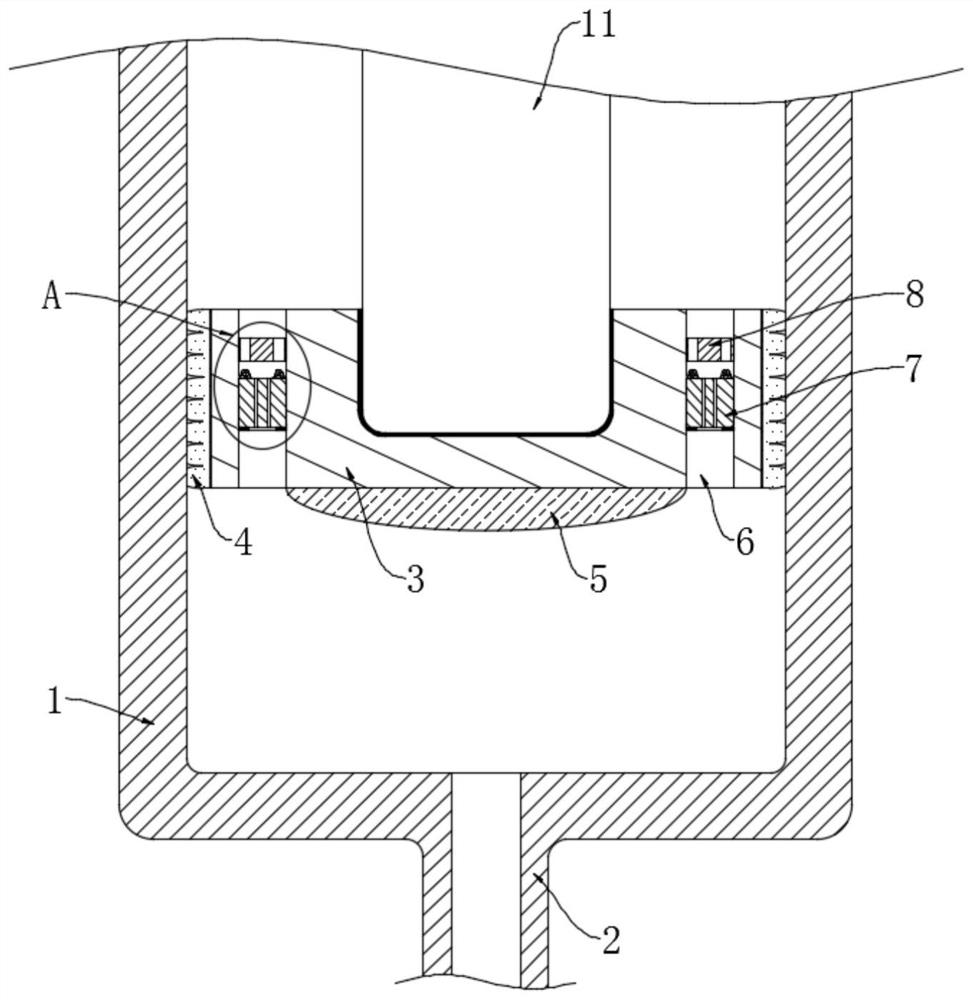
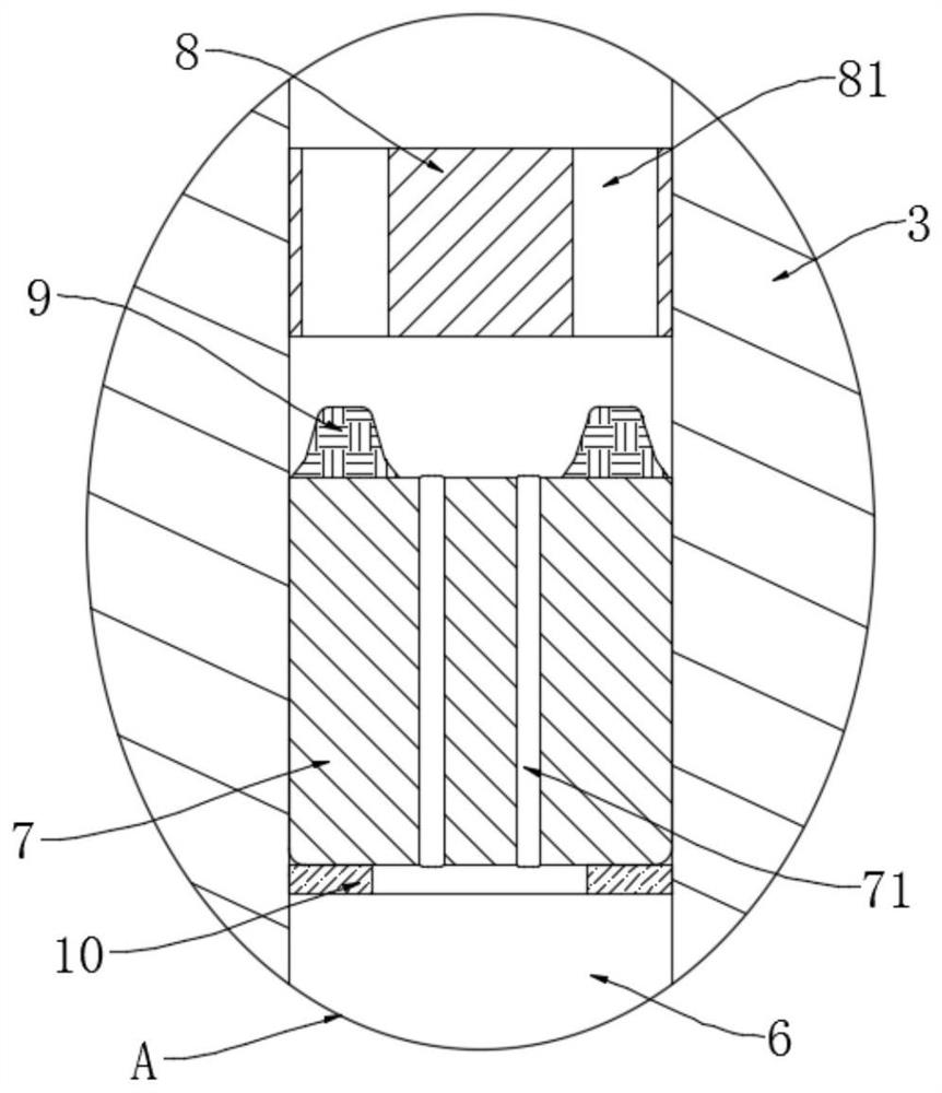
[0021] refer to Figure 1-2 , a self-venting type safety syringe, comprising a syringe 1 and a needle tube 2 fixedly connected to the syringe 1, a push rod 11 is placed inside the syringe 1, a fixing block 3 is provided at the lower end of the push rod 11, and the fixing block 3 A rubber stopper 4 is bonded to the inner wall of the syringe 1. The rubber stopper 4 acts as a seal. The bottom of the fixed block 3 is also provided with a guide plate 5. The edge of the guide plate 5 is tangent to the vertical groove 6, which can guide the gas. Flowing into the vertical groove 6, the fixed block 3 is provided with a plurality of vertical grooves 6, and a slider 7 is slidably installed in each vertical groove 6, and a plurality of first passages are symmetrically opened in the middle of each slider 7. Hole 71, the top of each slider 7 is symmetrically glued with a plurality of soft plugs 9, and each soft plug 9 does not overlap with the first through hole 71, and each vertical groove...

Embodiment 2

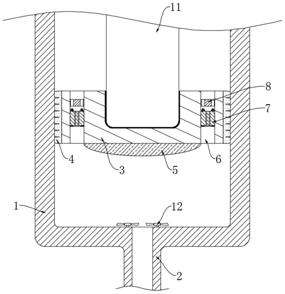
[0028] refer to Figure 3-4 The difference between this embodiment and Embodiment 1 is that: two turbulence fans 12 are symmetrically arranged at the connection between the needle tube 2 and the syringe 1, and each turbulence fan 12 includes a rotating shaft and a plurality of fan blades 121, and each Each fan blade 121 is made of elastic vibrating piece and is twisted. A plurality of needles 122 are distributed on the upper surface of each fan blade 121 . The needles 122 are close to the outside of the fan blade 121 .

[0029] This embodiment can illustrate its functional principle through the following operation mode: when the push rod 11 is pressed to make the liquid medicine flow to the needle tube 2, because the diameter difference between the needle tube 1 and the needle tube 2 is relatively large, the liquid medicine will enter the needle tube At 2 o'clock, there will be an obvious angle change, thereby promoting the fan blade 121 of the spoiler fan 12, causing the spoi...


PUM


Abstract

The invention discloses a self-exhausting type safe injector. The self-exhausting type safe injector comprises a needle cylinder and a needle tube fixedly connected with the needle cylinder, wherein apush rod is placed in the needle cylinder, a fixing block is arranged at the lower end of the push rod, a rubber plug is bonded to the joint of the fixing block and the inner wall of the needle cylinder, and a plurality of vertical grooves are formed in the fixing block in a penetrating manner; a sliding block is mounted in each vertical groove in a sliding manner, a plurality of first through holes are symmetrically formed in the middle of each sliding block, a plurality of soft plugs are symmetrically connected to the top of each sliding block in a glued manner, each soft plug does not coincide with the corresponding first through hole, and a blocking ring and a limiting ring are fixedly arranged in each vertical groove; and each blocking ring and the corresponding limiting ring which are located in the same vertical groove are located above and below the corresponding sliding block, and a plurality of second through holes are symmetrically formed in each blocking ring. Before liquid medicine injection, a manual defoaming operation is not needed, the injection efficiency and the injection effect are not affected, and besides, liquid medicine waste cannot be caused.

Description

technical field [0001] The invention relates to the technical field of syringes, in particular to a self-venting safety syringe. Background technique [0002] When using a syringe to inject medicinal liquid, it is usually used for subcutaneous injection or intravenous injection. When the medical staff extracts the medicinal liquid from the medicine bottle, air is easily mixed into the syringe from the needle tube. If the air is not discharged from the syringe before injection , In the process of subcutaneous injection, it is easy to cause hard knots on the skin, which will make the patient feel uncomfortable. If more air is mixed in during intravenous injection, it may cause venous embolism, and even shock, death and other serious consequences. [0003] The method for the medical staff to discharge the air in the syringe is to lift the syringe, then tap the syringe lightly, so that the air in the liquid medicine will gather at the needle tube, and then push the piston to exp...

Claims


Application Information

Patent Timeline
Patent Type & Authority Applications(China)
IPC IPC(8): A61J1/20A61M5/178
CPCA61J1/2096A61M5/178A61J1/2003A61J1/2068
Inventor 陆明京
Owner 陆明京
Why Eureka
Try Eureka