
Hot melt adhesive dispensing valve

A technology of dispensing valves and hot melt adhesives, which is applied in the direction of coatings, devices for coating liquids on surfaces, etc., and can solve problems such as not being affected by each other

Inactive Publication Date: 2021-01-12
詹爱平
View PDF1 Cites 2 Cited by
  • Summary
  • Abstract
  • Description
  • Claims
  • Application Information

AI Technical Summary

Problems solved by technology

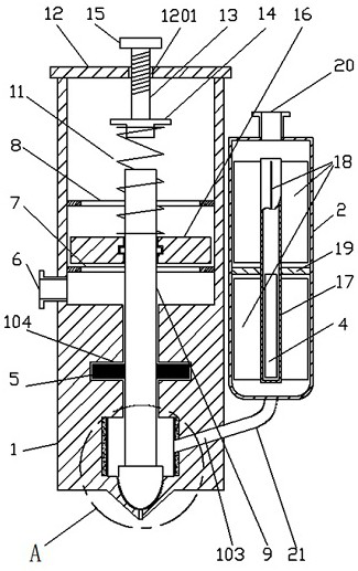
[0004] The technical problem to be solved by the present invention is to provide a reasonable structure for some problems of the above-mentioned device, so that the heating zones do not affect each other, so that the internal glue is controlled at a high temperature stage when a high temperature is required. When the medium temperature is required for a certain period of time, it is controlled in the medium temperature stage, and when the product is low temperature, it is controlled in the low temperature stage, that is, the segmented heating areas do not affect each other, and the glue in each area is heated evenly, and the fluidity is good without clogging. Finally, a hot melt glue dispensing valve that can conveniently adjust the glue output

Method used


Image

  • Hot melt adhesive dispensing valve
  • Hot melt adhesive dispensing valve
  • Hot melt adhesive dispensing valve

Examples


Embodiment Construction

[0021] The technical solutions in the embodiments of the present invention will be clearly and completely described below in conjunction with the drawings in the present invention. Apparently, the described embodiments are only some of the embodiments of the present invention, not all of them. Based on the embodiments of the present invention, all other embodiments obtained by persons of ordinary skill in the art without making creative efforts belong to the protection scope of the present invention. If the words "up", "down", "left" and "right" appear in the following, it only means that they are consistent with the directions of up, down, left and right in the drawings themselves, and do not limit the structure.

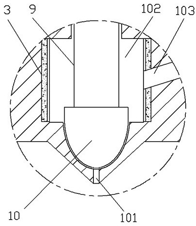
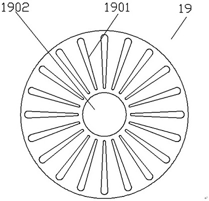
[0022] like figure 1 A hot-melt glue dispensing valve shown includes a valve body 1 and a rubber cartridge 2, the valve body 1 is used to realize the dispensing action, the glue cartridge 2 is used to store the glue, and the further glue cartridge 2 is also used in...


PUM


Abstract

The invention discloses a hot melt adhesive dispensing valve, and belongs to the technical field of mechanical equipment. According to the hot melt adhesive dispensing valve, an adhesive cylinder is arranged on the outer side of a valve body, and a copper pipe at the center inside the adhesive cylinder and heat conduction fins extending to the periphery on the outer side surface of the copper pipeare used for heat transfer, so that the heating area of adhesive in the adhesive cylinder is increased, the adhesive is heated more uniformly, and the frequency of blockage caused by the uneven heating of fluid is reduced; a heating rod in the copper pipe preheats the adhesive at low and medium temperatures, an adhesive storage cavity, away from the adhesive cylinder, in the valve body is a high-temperature heating area, and the interference between the heating rod and the high-temperature heating area is avoided; and a spring seat is moved downwards to compress a spring by rotating a threaded rod, so that the compression amount of the spring is changed, the greater the compression amount of the spring is, the greater the elastic force of the spring is, then the speed of pushing a pressing head to move downward is changed, the earlier the pressing head blocks an adhesive outlet, the less adhesive flows out, on the contrary, the lower the moving speed is and the later the pressing headblocks the adhesive outlet, the more adhesive flows out, and the adjustment of the adhesive outlet is achieved.

Description

technical field [0001] The invention belongs to the technical field of mechanical equipment, and in particular relates to a hot-melt glue dispensing valve. Background technique [0002] Most of the dispensing valves of existing dispensing machines use a single-temperature zone heating system, that is, the entire rubber cylinder is heated at one temperature from top to bottom. For hot-melt PUR glue, it can be divided into two types according to its chemical composition, one is polyether PUR glue is sensitive to temperature. The use temperature is around 80°C. Prolonged heating will easily lead to the deterioration and decomposition of the polymer cross-linking structure of the glue. However, long-term (more than 2 hours) heating at high temperatures will also cause chemical reactions in the glue to degrade and decompose the polymer crosslinking structure. At the same time, the color masterbatch in the glue will decompose and change color, which will seriously affect the appea...

Claims


Application Information

Patent Timeline
Patent Type & Authority Applications(China)
IPC IPC(8): B05C5/02B05C11/10
CPCB05C5/0225B05C11/1042
Inventor 詹爱平
Owner 詹爱平
Learn More