Stainless steel panel cutting and positioning die

A technology for positioning molds and stainless steel, applied in manufacturing tools, welding equipment, laser welding equipment, etc., can solve problems such as insufficient positioning accuracy, insufficient positioning stability, cutting deviation, etc., to achieve good cutting effect, improve cutting accuracy, and accurate positioning. Effect

Inactive Publication Date: 2021-01-12
江门市冠奇不锈钢制品有限公司
View PDF0 Cites 1 Cited by
  • Summary
  • Abstract
  • Description
  • Claims
  • Application Information

AI Technical Summary

Problems solved by technology

[0002] In the production process of stainless steel panels, it is often necessary to cut them. The cutting process includes opening, trimming, chamfering, etc. In practical applications, we need stainless steel panels of different sizes, so we need to cut stainless steel panels. However, the current cutting and positioning molds are not stable enough in positioning, and the positioning is not accurate enough, which makes the cutting deviation and causes losses.

Method used


Image

  • Stainless steel panel cutting and positioning die
  • Stainless steel panel cutting and positioning die
  • Stainless steel panel cutting and positioning die

Examples


Embodiment 1

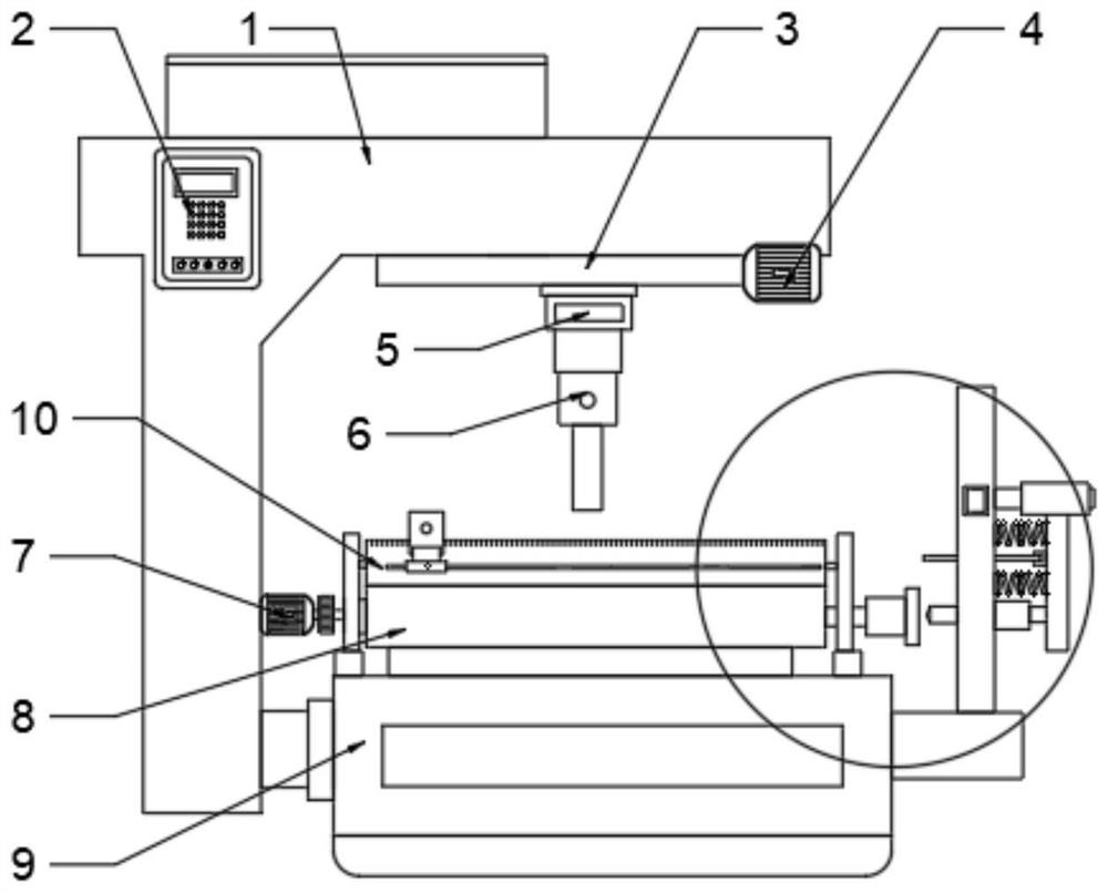
[0021] see Figure 1~3 , in an embodiment of the present invention, a stainless steel panel cutting and positioning mold includes a workbench 9; a work frame 1 is fixedly installed on one side of the work table 9; an operation panel 2 and a laser cutting mechanism are installed on the work frame 1 A transmission mechanism 8 is installed on the top of the worktable 9; a mold shell 10 is provided on the worktable 9; a positioning mechanism is provided on one side of the workbench 9 corresponding to the transmission mechanism 8.

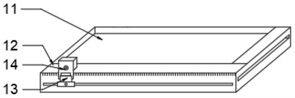
[0022] Further, the mold shell 10 includes a mold cavity 11 and a mounting plate 12; the mold cavity 11 is clamped with a stainless steel plate; the mounting plate 12 is provided with a locator 13; the front of the mold shell 10 is provided with scale.

[0023] Further, the back of the positioner 13 is provided with a limit sliding block; the front of the positioner 13 is provided with an infrared light emitting lamp 14; the corresponding limit slide o...

Embodiment 2

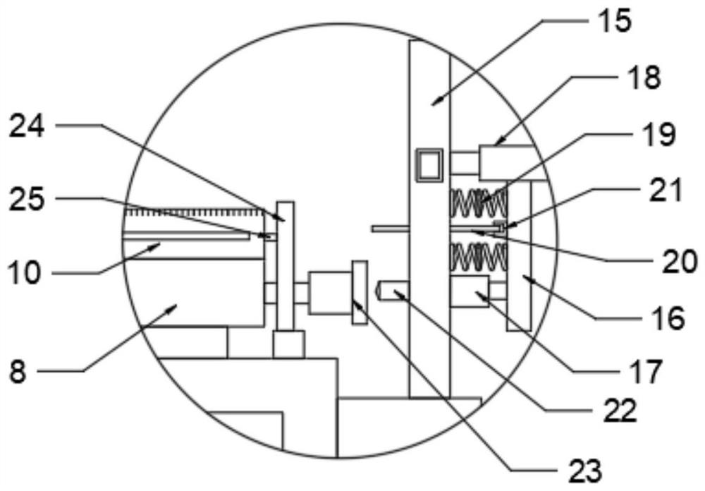
[0028] see image 3 , the top of the workbench 9 is equipped with a guide frame 24; the guide frame 24 is equipped with a guide block 25 near the side of the mold shell 10; the corresponding guide block 25 is provided with a limit chute on the mold shell 10; through the guide The arrangement of the block 25 and the limit chute prevents the mold shell 10 from shifting when cutting.

[0029]The working principle of the present invention is: through the setting of No. 1 guide rail 3, No. 1 servo motor 4 and longitudinal adjustment mechanism 5, it is convenient for laser cutting edge 6 to cut; through the cooperation of photoelectric sensor and infrared light emitting lamp 14, accurate positioning and cutting are performed; The rotation of the eccentric wheel 20 driven by the micro servo motor can change the distance between the installation fixed plate 16 and the fixed plate 15, and then change the position of the positioning head 22. When cutting is required, the positioning hea...


PUM


Abstract

The invention discloses a stainless steel panel cutting and positioning die which comprises a worktable. A working frame is fixedly mounted on one side of the worktable; an operation panel and a lasercutting mechanism are mounted on the working frame; a transmission mechanism is mounted at the top of the worktable; a die shell is arranged on the worktable; and a positioning mechanism corresponding to the transmission mechanism is arranged on one side of the worktable. The stainless steel panel cutting and positioning die is convenient to use, accurate in positioning, high in cutting stabilityduring cutting and good in cutting effect.

Description

technical field [0001] The invention relates to the technical field of panel cutting, in particular to a stainless steel panel cutting positioning mold. Background technique [0002] In the production process of stainless steel panels, it is often necessary to cut them. The cutting process includes opening, trimming, chamfering, etc. In practical applications, we need stainless steel panels of different sizes, so we need to cut stainless steel panels. However, the current cutting and positioning molds are not stable enough in positioning, and the positioning is not accurate enough, which makes the cutting deviation and causes losses. [0003] Therefore, in view of the above present situation, it is urgent to develop a stainless steel panel cutting positioning mold. Contents of the invention [0004] The object of the present invention is to provide a stainless steel panel cutting and positioning mold to solve the problems raised in the above-mentioned background technolog...

Claims


Application Information

Patent Timeline
Patent Type & Authority Applications(China)
IPC IPC(8): B23K26/38B23K26/70
CPCB23K26/38B23K26/702
Inventor 李锡其
Owner 江门市冠奇不锈钢制品有限公司
Why Eureka
Try Eureka