
Floating taper sleeve centering clamp

A technology of centering fixtures and taper sleeves, applied in clamping, positioning devices, manufacturing tools, etc., can solve problems such as high scrap rate and poor verticality tolerance, achieve accurate centering, and improve processing accuracy and efficiency Effect

Active Publication Date: 2021-01-12
福建省威诺数控有限公司
View PDF13 Cites 3 Cited by
  • Summary
  • Abstract
  • Description
  • Claims
  • Application Information

AI Technical Summary

Problems solved by technology

[0006] In order to solve the problem in the prior art that the verticality tolerance between the joint surface of the motor and the joint surface below is not guaranteed and the rejection rate is high, the present invention provides a centering fixture for a floating taper sleeve, which uses a conical centering device and a positioning The devices act at the same time to solve the above problems

Method used


Image

  • Floating taper sleeve centering clamp
  • Floating taper sleeve centering clamp
  • Floating taper sleeve centering clamp

Examples


Embodiment 1

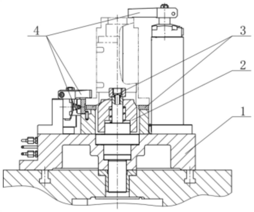
[0039] Such asfigure 1 As shown, a floating taper sleeve centering fixture includes a base 1, a centering device 2, a positioning device 3 and a clamping device 4, the positioning device 3 is arranged on the upper surface of the base 1, and the centering device 2 is vertically arranged on the The upper surface of the base 1 is arranged inside the positioning device 3 , and the clamping device 4 is arranged on the upper surface of the base 1 .

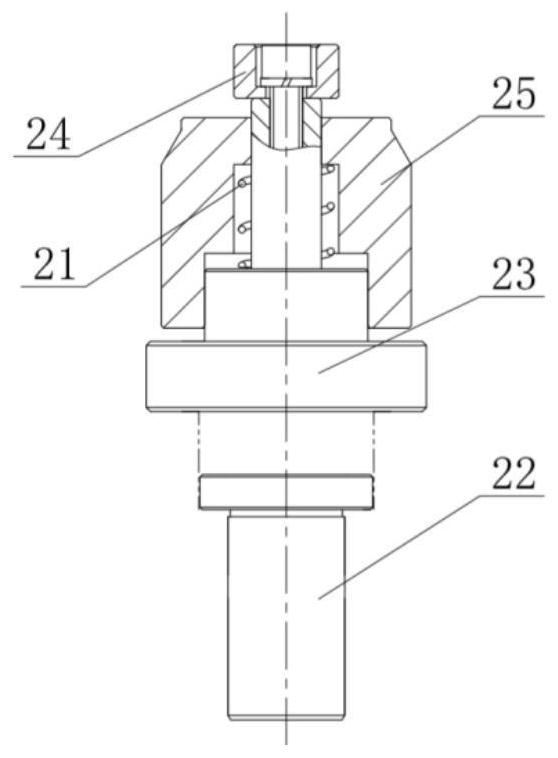
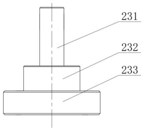
[0040] Such as figure 2 As shown, the centering device 2 includes a rotating shaft 22, a centering seat 23, a spring 21, a taper sleeve 25 and a pressing block 24, and the rotating shaft 22, the centering seat 23, the spring 21, the taper sleeve 25 and the pressing block 24 are coaxial , the rotating shaft 22 is arranged on the upper end of the base 1 and is vertical to the upper surface of the base 1, the centering seat 23 is arranged on the upper end of the rotating shaft 22, the spring 21 is nested on the upper end of the centering ...


PUM


Abstract

The invention provides a floating taper sleeve centering clamp. The floating taper sleeve centering clamp comprises a base, a centering device, a positioning device and a clamping device, wherein thepositioning device is arranged on the upper surface of the base; the centering device is vertically arranged on the upper surface of the base and is arranged on the inner side of the positioning device; the centering device comprises a rotating shaft, a centering seat, a spring, a taper sleeve and a pressing block; the rotating shaft, the centering seat, the spring, the taper sleeve and the pressing block are coaxial; the rotating shaft is arranged at the upper end of the base and is perpendicular to the upper surface of the base; the centering seat is arranged at the upper end of the rotatingshaft; the spring is nested at the upper end of the centering seat; the outer side of the taper sleeve is a conical surface and is axially provided with a through hole; the spring is arranged in thethrough hole of the taper sleeve; the upper end of the centering seat penetrates through the taper sleeve; and the pressing block is arranged at the top end of the centering seat. a motor positioningseam allowance and the floating taper sleeve cooperate to center, so that the perpendicularity allowance between a motor joint surface and a lower joint surface is ensured; a thrust oil cylinder is used for aligning so as to limit the rotation freedom degrees of the workpieces; joint screw counter bores of the motor are symmetrical about the center of the clamp tool; and machining precision and efficiency of the workpieces are greatly improved.

Description

technical field [0001] The invention relates to the field of machine tool fixtures, in particular to a centering fixture. Background technique [0002] The centering clamping mechanism is a clamping mechanism that realizes the centering positioning and clamping of the workpiece at the same time, that is, during the clamping process, it can keep the workpiece symmetrical with respect to a certain axis or a certain plane of symmetry. In the case of uncertain positioning hole size, the centering mechanism is often not accurate. [0003] The original process on the motor seat: Alignment on the ordinary horizontal milling machine to complete the milling of the motor joint surface and the square outline; external alignment and then milling the joint surface of the stop block; end milling and milling the joint surface of the cover plate; The cover plate is used as the datum plane to mill the joint surface of the workpiece and the workpiece below; the joint surface is used as the p...

Claims


Application Information

Patent Timeline
IPC IPC(8): B23Q3/12
CPCB23Q3/082Y02P70/10
Inventor 金丽英毕伟峰余乐烽林军佘智群
Owner 福建省威诺数控有限公司
Learn More