
Transmission shaft flange grinding device for machining mechanical parts

A technology for mechanical parts and transmission shafts, applied in the field of transmission shaft flange grinding devices, can solve the problems of poor fixation stability, low efficiency, and inability to realize harmful gas absorption and purification in linkage, and achieve the effect of improving the expansion and contraction range.

Inactive Publication Date: 2021-01-12
陶永华
View PDF6 Cites 3 Cited by
  • Summary
  • Abstract
  • Description
  • Claims
  • Application Information

AI Technical Summary

Problems solved by technology

[0007] In order to solve the above-mentioned technical problems, the present invention provides a transmission shaft flange grinding device for mechanical parts processing, to solve the existing problem that the existing device cannot realize the synchronization of various fixing structures when fixing the transmission shaft flange It is fixed, and the fixing stability is poor; moreover, the efficiency of the existing device is low when grinding, and the grinding structure cannot be improved to realize the improvement of the grinding area, and the grinding structure cannot be improved to realize the protection of the drive shaft flange type grinding; finally, the existing device cannot be linked to realize the absorption and purification of harmful gases during the grinding process

Method used


Image

  • Transmission shaft flange grinding device for machining mechanical parts
  • Transmission shaft flange grinding device for machining mechanical parts
  • Transmission shaft flange grinding device for machining mechanical parts

Examples


Embodiment

[0035] as attached figure 1 to attach Figure 8 Shown:

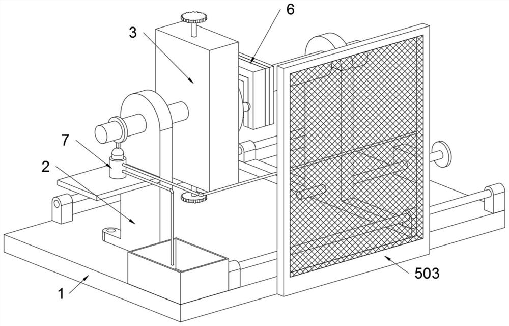
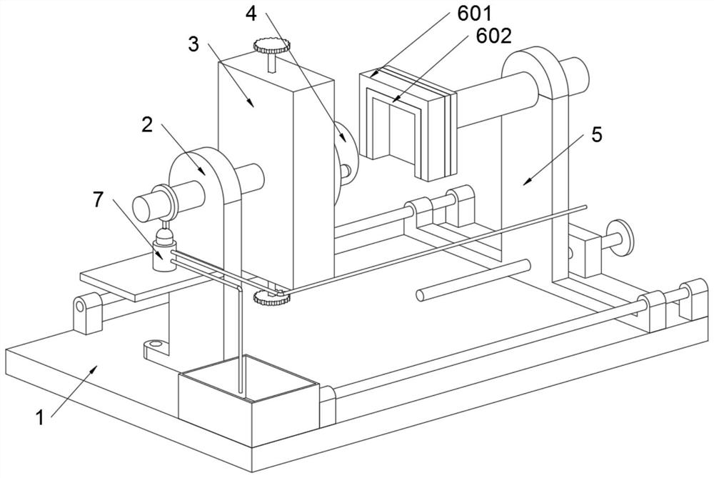
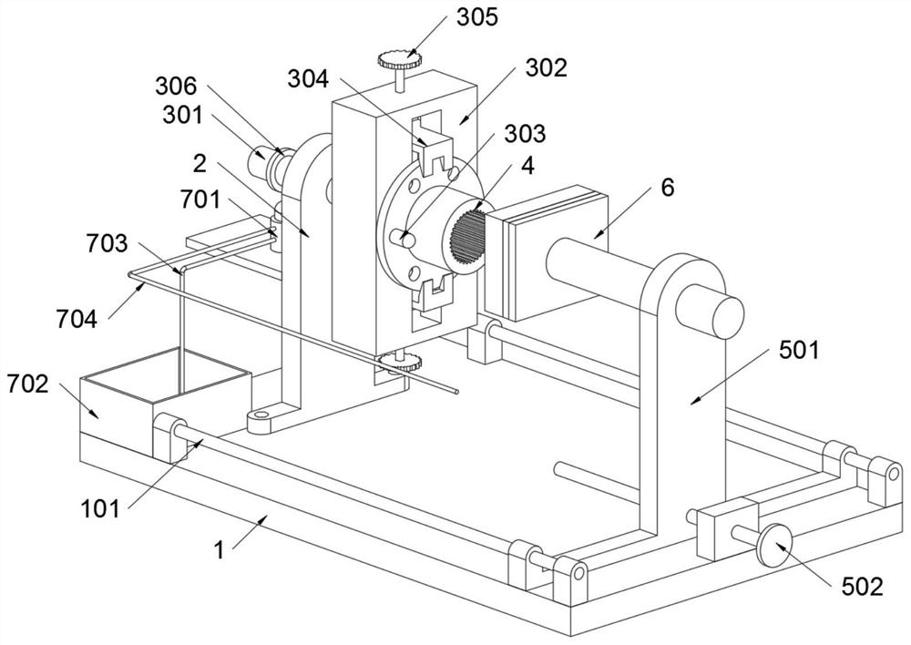
[0036] The invention provides a transmission shaft flange grinding device for processing mechanical parts, comprising a base 1 and an elastic telescopic bottle 701; the base 1 is fixedly connected with a mounting seat 2 by bolts, and the mounting seat 2 is rotatably connected with a fixed Structure 3, and the transmission shaft flange 4 is fixed on the fixed structure 3; the adjustment structure 5 is arranged on the base 1, and the grinding structure 6 is welded on the adjustment structure 5; the purification structure 7 is installed on the mounting base 2; refer to as figure 2 and image 3, the grinding structure 6 includes a grinding seat 601 and a grinding block 602, the grinding seat 601 is welded on the main body seat 501, and a grinding block 602 is adhered in the grinding seat 601; both the grinding seat 601 and the grinding block 602 are concave structures, and the grinding Block 602 inner wall is in contact ...


PUM


Abstract

The invention provides a transmission shaft flange grinding device for machining mechanical parts, relates to the technical field of grinding devices, and solves the problems that during fixing, synchronous fixing of multiple fixing structures cannot be achieved, fixing stability is poor, grinding area cannot be increased, protective grinding of a flange of a transmission shaft cannot be achieved,and absorption and purification of harmful gas cannot be achieved in a linkage mode in a polishing process. The transmission shaft flange grinding device for machining the mechanical parts comprisesa base and an elastic telescopic bottle; and a mounting seat is fixedly connected to the base through bolts. A grinding base and a grinding block are both of the concave structure, and the inner wallof the grinding block makes contact with the flange of the transmission shaft, so that during grinding, on one hand, the grinding base and the grinding block of the concave structure can form a disengaged protection structure of the flange of the transmission shaft, on the other hand, the grinding base and the grinding block of the concave structure can increase contact area with the flange of thetransmission shaft, and thus the grinding efficiency is improved.

Description

technical field [0001] The invention belongs to the technical field of grinding devices, and more specifically relates to a grinding device for driving shaft flanges used for machining mechanical parts. Background technique [0002] The flange of the transmission shaft is used to connect with the transmission shaft, and the flange of the transmission shaft needs to be polished after processing. [0003] For example, the application number: CN202010638548.4, the present invention provides a grinding device, which includes: a column; a first swing arm, which is sleeved on the column, and the first swing arm is adapted to be able to rotate relative to the column; Two swing arms are rotatably arranged on the end of the first swing arm away from the column; the grinding assembly is arranged on the second swing arm. The grinding device provided by the invention has the advantages of simple operation, low technical requirements, flexible and changeable grinding action, which can s...

Claims


Application Information

Patent Timeline
IPC IPC(8): B24B9/04B24B41/06B24B55/06B24B55/00B24D7/18
CPCB24B9/04B24B41/06B24B55/00B24B55/06B24D7/18
Inventor 陶永华
Owner 陶永华
Learn More