Uniform segmented cutting equipment for logs for building materials
A cutting equipment and uniform technology, which is applied in the field of uniform and segmented cutting equipment for building materials, can solve the problems of single function, time-consuming and labor-intensive, and achieve the effect of uniform specifications and improved work efficiency.
- Summary
- Abstract
- Description
- Claims
- Application Information
AI Technical Summary
Problems solved by technology
Method used
Image
Examples
Embodiment 1
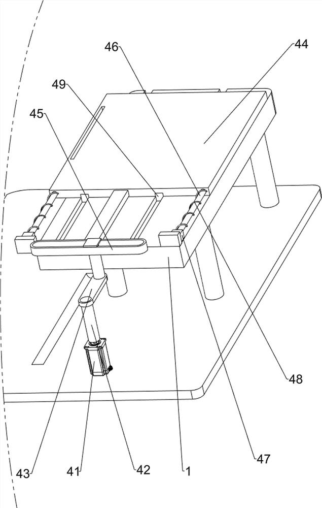
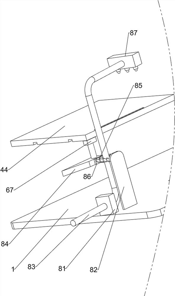
[0072]A cutting equipment for round logs for building materials, such asfigure 1 As shown, it includes a base 1, a cutting mechanism 2, a material blocking mechanism 3, a material pushing mechanism 4, and a material ejecting mechanism 5. The right side of the base 1 is connected with a cutting mechanism 2, and the right side of the base 1 is connected with a material blocking mechanism 3, and a cutting mechanism 2 is located below the stopper mechanism 3, a pushing mechanism 4 is connected to the left side of the base 1, and a pushing mechanism 5 is connected to the pushing mechanism 4.
[0073]When people need to cut logs, they first place the logs on the ejector mechanism 5 and the pusher mechanism 4, and then start the cutting mechanism 2 and the components of the pusher mechanism 4, so that the pusher mechanism 4 continuously pushes the log and makes the cutting The mechanism 2 cuts the log. After completion, the log is taken out, and the parts of the cutting mechanism 2 and the pu...
Embodiment 2
[0075]On the basis of Example 1, such asFigure 2 to Figure 4 As shown, the cutting mechanism 2 includes a first servo motor 21, a bearing seat 22, a first rotating shaft 23, a second rotating shaft 24, a bevel gear set 25, and a cutter 26. The first servo motor 21 is connected to the right front side of the base 1 and the first The output shaft of the servo motor 21 is connected with a first rotating shaft 23, the front right side of the base 1 is connected with a bearing seat 22, the bearing seat 22 is located on the left side of the first servo motor 21, the upper part of the bearing seat 22 is rotatably connected with a second rotating shaft 24, the second rotating shaft A bevel gear set 25 is connected between the right side of 24 and the top of the first rotating shaft 23, and a cutter 26 is connected to the left side of the second rotating shaft 24.
[0076]When the log needs to be cut, the first servo motor 21 is started. The output shaft of the first servo motor 21 rotates to d...
Embodiment 3
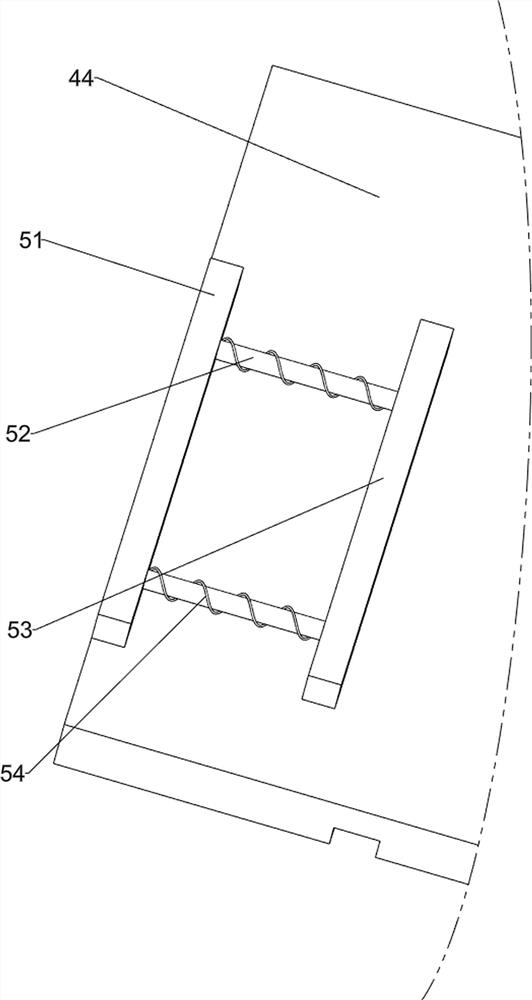
[0082]On the basis of Example 2, such asFigure 5 to Figure 8As shown, the ejector mechanism 5 includes a first fixed plate 51, a second telescopic rod 52, a push plate 53, and a second spring 54. The top left side of the moving plate 44 is connected to a first fixed plate 51, and the first fixed plate 51 is connected to the right. A second telescopic rod 52 is connected to the front and rear sides of the second telescopic rod 52, and a push plate 53 is connected between the right side of the second telescopic rod 52. The front and rear sides of the right part of the first fixed plate 51 and the front and rear sides of the left part of the push plate 53 are both connected. A second spring 54 is connected, and the second spring 54 is sleeved outside the second telescopic rod 52.
[0083]When the log needs to be cut, the push plate 53 is moved to the left, the second spring 54 and the second telescopic rod 52 are compressed, and then the log is placed on the moving plate 44, let go, and u...
PUM
 Abstract
Description
Claims
Application Information
 - R&D
- Intellectual Property
- Life Sciences
- Materials
- Tech Scout
- Unparalleled Data Quality
- Higher Quality Content
- 60% Fewer Hallucinations
Browse by: Latest US Patents, China's latest patents, Technical Efficacy Thesaurus, Application Domain, Technology Topic, Popular Technical Reports.
© 2025 PatSnap. All rights reserved.Legal|Privacy policy|Modern Slavery Act Transparency Statement|Sitemap|About US| Contact US: help@patsnap.com


