Obstacle crossing wheel device and self-walking robot

An obstacle-crossing wheel and robot technology, applied in the field of robots, can solve the problems of limited friction, low obstacle-crossing ability, and the groove cannot be made too deep, and achieves the effects of high reliability, low cost and simple structure.

Pending Publication Date: 2021-01-12
MIDEA ROBOZONE TECH CO LTD
View PDF6 Cites 6 Cited by
  • Summary
  • Abstract
  • Description
  • Claims
  • Application Information

AI Technical Summary

Problems solved by technology

However, the friction generated by this method is limited, and higher obstacles cannot be climbed; since the tire is a soft material, the groove cannot be made too deep, and when the groove is shallow, the ability to grasp the edge of the obstacle is low, and the ability to overcome obstacles is low

Method used


Image

  • Obstacle crossing wheel device and self-walking robot
  • Obstacle crossing wheel device and self-walking robot
  • Obstacle crossing wheel device and self-walking robot

Examples


no. 1 example

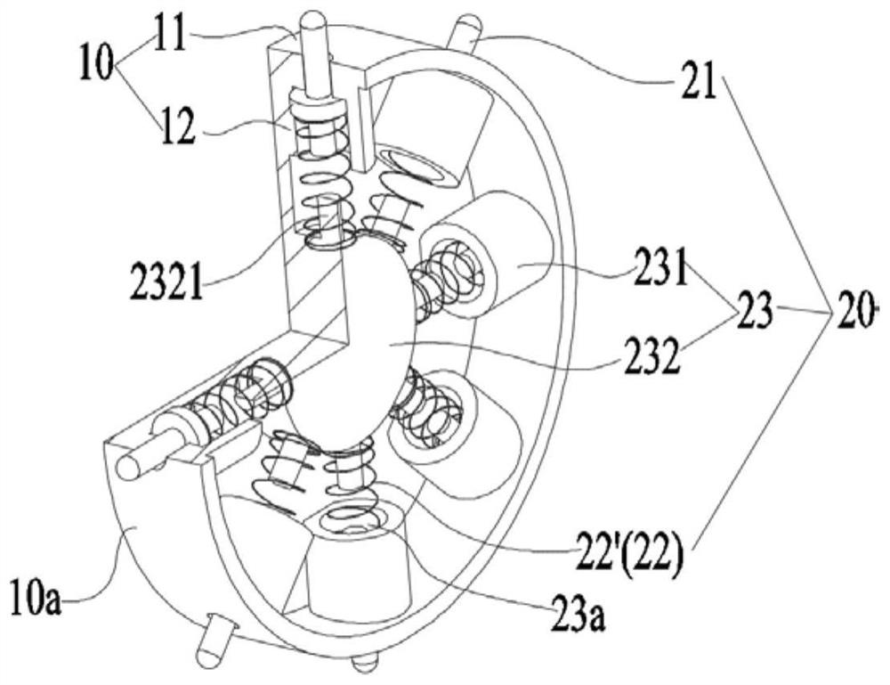
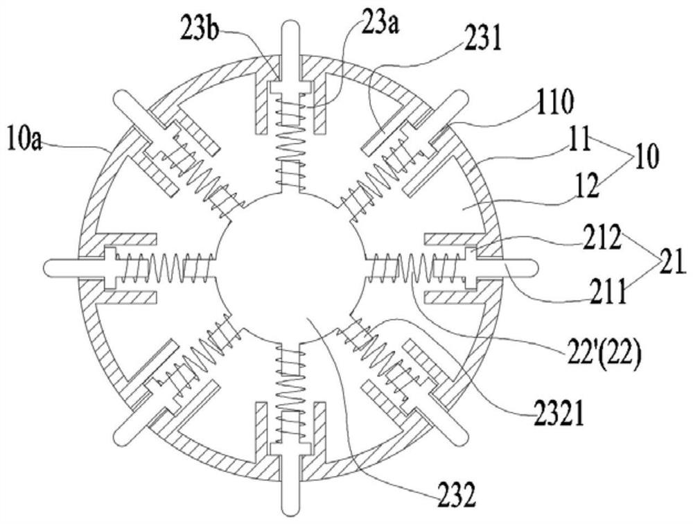
[0052] see Figure 1 to Figure 4 , The legs 21 and the wheel body 10 are combined with each other. Specifically, the outer edge portion 11 is formed with a chute 110 passing through the outer edge portion 11, and the legs 21 are slidably inserted in the chute 110, that is to say, the legs 21 are located inside the outer edge portion 11, and the legs 21 In the process of extending outward along the wheel body 10 , the outer edge portion 11 needs to be penetrated.

[0053] In this embodiment, the elastic member 22 applies a force toward the outside of the wheel body 10 to the leg 21 in a compressed state. Specifically, in this embodiment, the elastic member 22 is a compression spring 22', and the compression spring 22' can make the supporting leg 21 have a larger sliding range.

[0054] see figure 1 The mounting seat 23 includes a guide sleeve 231 and a seat body 232 , wherein the seat body 232 is located on the inside of the guide sleeve 231 along the wheel body 10 , and the...

no. 2 example

[0062] see Figure 5 , the structure of this embodiment is generally the same as that of the first embodiment. The difference from the first embodiment is that in this embodiment, the elastic member 22 exerts an effect on the leg 21 towards the outside of the wheel body 10 in a stretched state. force. This embodiment is described by taking the elastic member 22 as a tension spring 22" as an example.

[0063] In this embodiment, the mounting base 23 is roughly in the shape of a sleeve, one side of the mounting base 23 is fastened to the periphery of the chute 110, the avoidance hole 23b communicates with the chute 110 and is arranged coaxially, and the elastic member 22 is clamped at the limit Between the portion 212 and the inner surface of the outer edge portion 11 , opposite sides of the elastic member 22 are fastened to the limiting portion 212 and the outer edge portion 11 respectively. When the obstacle-crossing wheel device is not subjected to external force, the elast...

no. 3 example

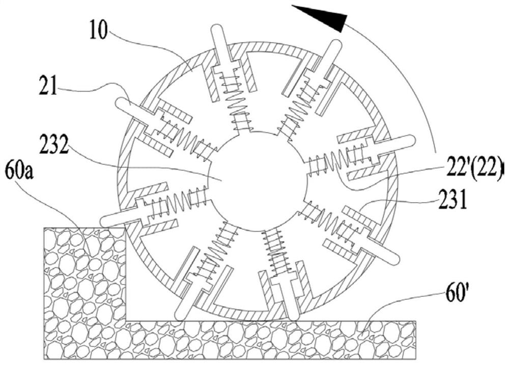
[0065] see Figure 6 to Figure 9The structure of this embodiment is generally the same as that of the first embodiment. The difference from the first embodiment is that the legs 21 are relatively independent from the wheel body 10. Specifically, the legs 21 are located at one side of the outer edge 11 along the rotation axis L. On the side, when the supporting legs 21 protrude outward along the wheel body 10 , they will not contact the outer edge portion 11 or interfere with the outer edge portion 11 . That is to say, in the third embodiment, the sliding groove 110 in the first embodiment is not provided on the outer edge portion 11 .

[0066] Specifically, in this embodiment, the guide sleeve 231 is disposed on the circumferential surface of the seat body 232, the elastic member 22 and the limiting portion 212 are located in the accommodating cavity 23a, the limiting portion 212 can abut against the surrounding of the escape hole 23b, and the elastic member 22 abuts between ...


PUM


Abstract

The embodiment of the invention provides an obstacle crossing wheel device and a self-walking robot. The obstacle crossing wheel device comprises a wheel body and an obstacle crossing assembly. The wheel body is provided with a rotating axis and a walking surface. The obstacle crossing assembly comprises a mounting base, supporting legs and elastic pieces, the mounting base and the wheel body synchronously rotate around the rotating axis, the supporting legs can slide in the inner-outer direction of the wheel body relative to the mounting base, and the elastic pieces apply acting force towardsthe outer side of the wheel body to the supporting legs so that the ends, away from the rotating axis, of the supporting legs can protrude out of the walking surface. According to the obstacle crossing wheel device, when the obstacle crossing wheel device encounters an obstacle, one end of each supporting leg abuts against the top surface of the obstacle, in the climbing process, overturning is conducted with the contact point of the supporting leg and the obstacle as the supporting point, the friction force between the wheel body and the obstacle is increased through the supporting point, and the obstacle crossing wheel device can be assisted in climbing over the obstacle.

Description

technical field [0001] The present application relates to the technical field of robots, in particular to an obstacle-crossing wheel device and a self-propelled robot. Background technique [0002] Taking the sweeping robot as an example, it often encounters some obstacles in the working environment, such as small steps, wires, etc. Due to insufficient obstacle-surpassing performance, the sweeping robot cannot enter the area blocked by obstacles for cleaning operations in many cases. [0003] The obstacle surmounting performance of the driving wheel itself is a key factor affecting the obstacle surmounting performance of the sweeping robot. Existing obstacle-crossing drive wheels, the tire surface is designed with a certain shape and a grooved tread pattern. When crossing an obstacle, the friction between the tire and the obstacle and the grooves in the tire surface tread pattern are mainly used to block the obstacle, so as to avoid the drive wheel from slipping. , thereby ...

Claims


Application Information

Patent Timeline
Patent Type & Authority Applications(China)
IPC IPC(8): B60B15/00B60B19/00A47L11/24A47L11/40
CPCB60B15/00B60B19/00A47L11/24A47L11/4072A47L11/4061
Inventor 郭辉韩瑾程福萍
Owner MIDEA ROBOZONE TECH CO LTD
Why Eureka
Try Eureka