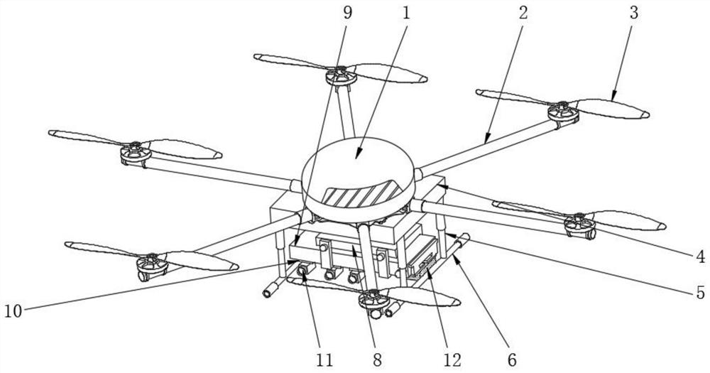
Six-rotor unmanned aerial vehicle surveying and mapping equipment for large-scale topographic survey
A technology for terrain surveying and unmanned aerial vehicles, applied in the field of unmanned aerial vehicles, can solve the problems of inconvenient carrying and adjustment of unmanned aerial vehicles, limited shooting angle of surveying and mapping equipment, poor practicability and functionality, etc. Efficiency and quality, longevity effect
- Summary
- Abstract
- Description
- Claims
- Application Information
AI Technical Summary
Problems solved by technology
Method used
Image
Examples
Embodiment 1
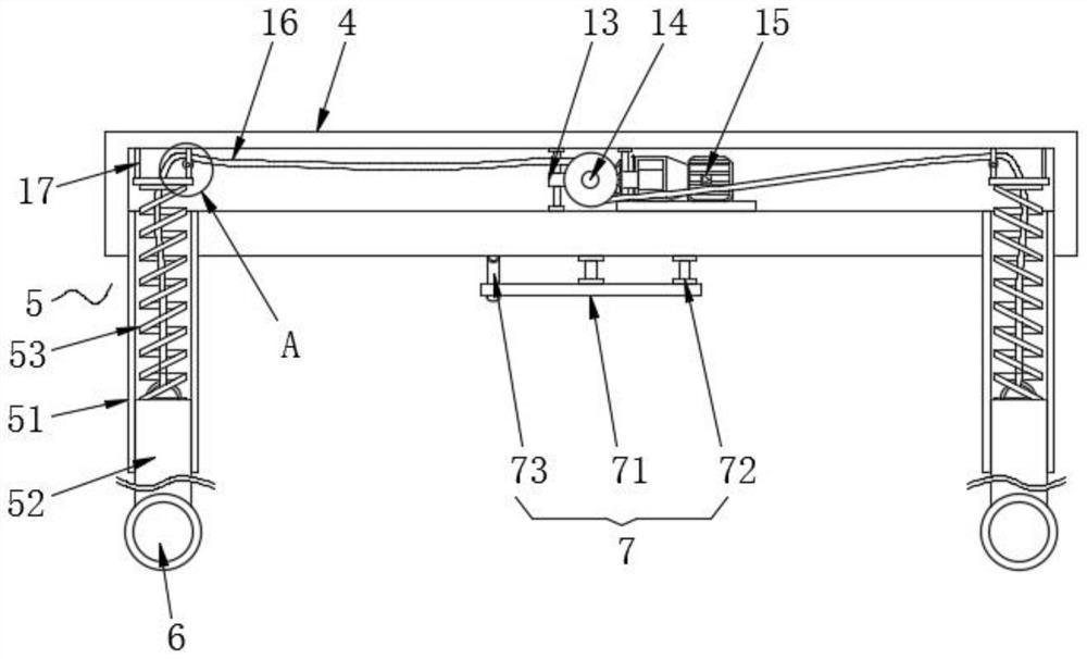
[0039] Slide the connecting frame 82 of the holder 8 into the anti-falling frame 7, the rotating rod 73 will be jacked up when the connecting frame 82 slides, and will rotate to the inside of the horizontal plate 71 after the connecting frame 82 slides away, and use bolts to Connecting frame 82 is connected with fixed box 4;
[0040] The installation frame 10 is installed in the inside of the installation box 9. When installing, the first assembly plate 101 in the installation frame 10 is slid along the connecting groove 93, and a high-resolution CCD digital camera is used as the surveying instrument 11. A high-resolution CCD digital camera is screwed to the middle part of the second assembly plate 102, the first assembly plate 101 and the installation box 9 through the second threaded hole 104 and the first threaded hole 94;
[0041] Attach the installation box 9 to the lower side of the holder 8, and then rotate the threaded rod 85 along the threaded groove 83. When the thre...
Embodiment 2
[0044] Slide the connecting frame 82 of the holder 8 into the anti-falling frame 7, the rotating rod 73 will be jacked up when the connecting frame 82 slides, and will rotate to the inside of the horizontal plate 71 after the connecting frame 82 slides away, and use bolts to Connecting frame 82 is connected with fixed box 4;
[0045] Unscrew the locking bolt 95, pull out the sliding box 92 from the assembly box 91, align the sliding box 92 and the first threaded hole 94 of the assembly box 91, and then tighten the locking bolt 95 to assemble the box 91 and the sliding box 92 Fix, then install the installation frame 10 to the inside of the installation box 9, when installing, slide the first assembly plate 101 in the installation frame 10 along the connection groove 93, adopt CCD digital camera, light optical camera and magnetic measuring instrument As the surveying instrument 11, use bolts to screw the CCD digital camera, light optical camera and magnetometer through the secon...
PUM
 Abstract
Description
Claims
Application Information
 - R&D
- Intellectual Property
- Life Sciences
- Materials
- Tech Scout
- Unparalleled Data Quality
- Higher Quality Content
- 60% Fewer Hallucinations
Browse by: Latest US Patents, China's latest patents, Technical Efficacy Thesaurus, Application Domain, Technology Topic, Popular Technical Reports.
© 2025 PatSnap. All rights reserved.Legal|Privacy policy|Modern Slavery Act Transparency Statement|Sitemap|About US| Contact US: help@patsnap.com


