Semi-automatic cable packaging equipment
A packaging equipment, semi-automatic technology, applied in packaging, transportation and packaging, packaging/bundling items, etc., can solve the problems of poor packaging effect and easy overpackaging
- Summary
- Abstract
- Description
- Claims
- Application Information
AI Technical Summary
Problems solved by technology
Method used
Image

Examples
Embodiment 1
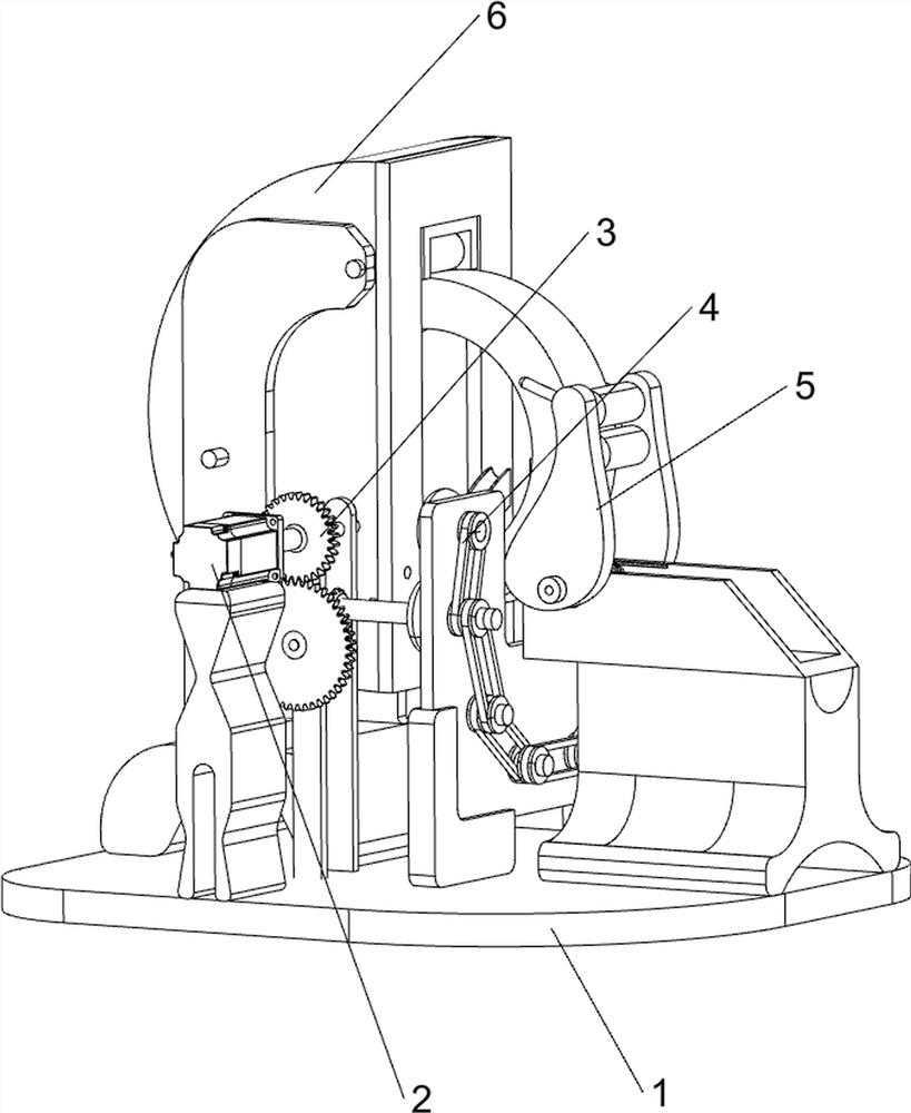
[0072] A semi-automatic cable packaging equipment, such as figure 1 As shown, it includes a bottom plate 1, a servo motor 2, a material rolling mechanism 3, a film sealing mechanism 4 and a clamping mechanism 5. A servo motor 2 is provided in the middle of the front side of the top of the bottom plate 1, and the output shaft of the servo motor 2 is connected to the top of the bottom plate 1. A rolling mechanism 3 is connected between them, and a film sealing mechanism 4 is provided on the middle side of the top of the base plate 1. The parts of the sealing film mechanism 4 are connected with the parts of the rolling mechanism 3, and the right side of the top of the bottom plate 1 is provided with a clamping mechanism 5.
[0073] When people need to pack the cables, people first move the parts of the clamping mechanism 5 by hand, and then put the cables that need to be packaged between the parts of the clamping mechanism 5 and the parts of the rolling mechanism 3. When people l...
Embodiment 2
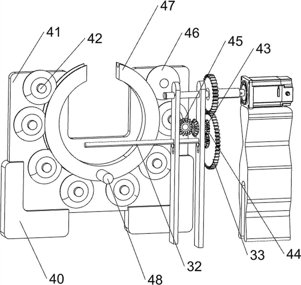
[0075] On the basis of Example 1, such as Figure 2-6 As shown, the rolling mechanism 3 includes a bearing seat 30, a first transmission shaft 31, a second transmission shaft 32, a first spur gear assembly 33, a first support frame 34, a support shell 35, a first roller 36, and a second roller 37 and the first support rod 38, two bearing blocks 30 are arranged on the front side of the top of the bottom plate 1, and the first transmission shaft 31 is connected in rotation between the tops of the bearing blocks 30, and the first transmission shaft 31 is connected with the output shaft of the servo motor 2 A second transmission shaft 32 is rotatably connected between the upper parts of the bearing housing 30, a first spur gear assembly 33 is connected between the front side of the second transmission shaft 32 and the first transmission shaft 31, and a second spur gear assembly 33 is connected between the front side of the second transmission shaft 32 and the first transmission sha...
Embodiment 3
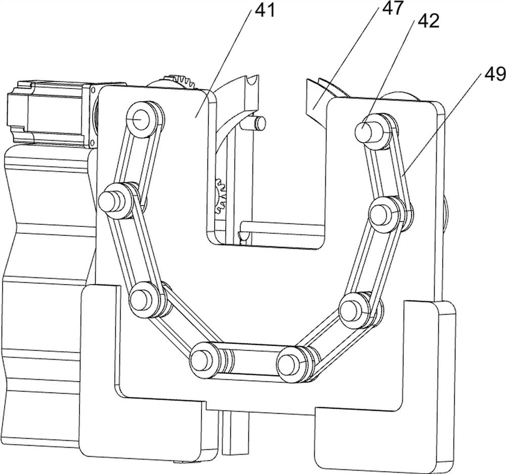
[0080] On the basis of Example 2, such as Figure 7 , Figure 8 and Figure 9 As shown, the clamping mechanism 5 includes a support seat 50, a feeding rack 51, a second support rod 52, a torsion spring 53, a support block 54, a third support rod 55, a third roller 56, a rotating block 57 and a limit rod 58, the right side of the top of the bottom plate 1 is provided with a support seat 50, and the top of the support seat 50 is provided with a loading rack 51, and a second support rod 52 is rotationally connected between the front and rear sides of the upper left side of the loading rack 51, and the second support rod 52 front and rear sides and between the front and rear sides of the loading rack 51 inner wall are connected with torsion spring 53, and torsion spring 53 is enclosed within on the second support rod 52, and the front and rear ends of the second support rod 52 are all connected with support block 54, support block 54, the third support rod 55 is connected betwee...
PUM
 Abstract
Description
Claims
Application Information
 - R&D
- Intellectual Property
- Life Sciences
- Materials
- Tech Scout
- Unparalleled Data Quality
- Higher Quality Content
- 60% Fewer Hallucinations
Browse by: Latest US Patents, China's latest patents, Technical Efficacy Thesaurus, Application Domain, Technology Topic, Popular Technical Reports.
© 2025 PatSnap. All rights reserved.Legal|Privacy policy|Modern Slavery Act Transparency Statement|Sitemap|About US| Contact US: help@patsnap.com