Cooling-to-energy aerospace engine

An engine and energy emission technology, applied in engine components, engine cooling, machine/engine, etc., can solve problems such as low efficiency, excessive volume, and small specific impulse of aerospace engines

Inactive Publication Date: 2021-01-12
曹建峰
View PDF0 Cites 2 Cited by
  • Summary
  • Abstract
  • Description
  • Claims
  • Application Information

AI Technical Summary

Problems solved by technology

[0003] The purpose of the present invention is to provide a cooling rotary energy aerospace engine to solve the technical problems of small specific impulse and low efficiency of the aerospace engine; it can also solve the technical problems of repeated use of the engine and excessive volume

Method used


Image

  • Cooling-to-energy aerospace engine
  • Cooling-to-energy aerospace engine

Examples


Embodiment Construction

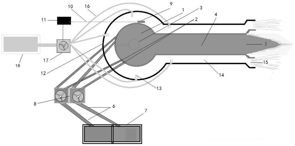
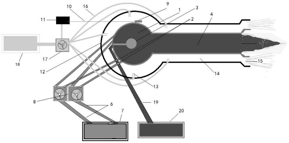
[0015] figure 1 It is a structural schematic diagram of the first embodiment of the present invention, showing that the energy chamber (combustion chamber) of the machine is injected with a mixture of oxygen and kerosene, and is ignited by the ignition device to perform work from the inner nozzle pipe and the inner nozzle, and the cooling cover sprays water to the gas. The energy chamber and the outer layer of the inner nozzle are cooled and converted into energy at the same time, and then the gas is ejected from the outer nozzle and the outer nozzle to do work; figure 2 same figure 1 , which shows that the energy chamber of the machine is injected with fluid working medium, and the energy emission device gives the working medium energy, which is sprayed out from the inner nozzle and the inner nozzle to do work, and at the same time, the cooling cover sprays water to cool the energy chamber and the outer layer of the inner nozzle. After the energy, the gas is ejected from th...


PUM


Abstract

The invention discloses a cooling-to-energy aerospace engine. An ignition or energy emission device is arranged in an energy chamber of the cooling-to-energy aerospace engine; small holes are distributed in the inner wall of the energy chamber and communicate with a working medium compression regulator and a working medium constant-temperature storage box through working medium guide pipes; the energy chamber is connected with an inner spray pipe and is provided with an inner nozzle; temperature detectors are arranged on the outer layers of the energy chamber and the inner spray pipe and communicate with a temperature controller through temperature signal wires; the energy chamber and the inner spray pipe are sleeved with a cooling cover; a cavity is formed between the energy chamber and the inner spray pipe to form a sleeve type outer spray pipe and an outer nozzle; small-hole spray pipes are distributed on the inner wall of the cooling cover; and one end of each small-hole spray pipeis connected with a water pressure regulator and a constant-temperature water tank through cooling water pipes. According to the engine, the cooling cover, the pipelines and other devices convert heat dissipation into propulsion energy, the temperature of the energy chamber and the temperature of the inner spray pipe are greatly increased, and the specific impulse is increased; the structure andthe control difficulty are reduced, repeated use is achieved, the size and the weight are reduced, the manufacturing, maintaining and using costs are low, and the engine is applicable to various spacetasks.

Description

technical field [0001] The invention relates to an aerospace engine. Background technique [0002] At present, aerospace engines in the true sense do not exist, and the existing so-called aerospace planes have not achieved interplanetary flight, but only realized round-trip flights on the ground, in the atmosphere and in low-earth orbits outside the atmosphere, and this round-trip is useful for large-scale The aircraft is brought into high altitude, and then sent into space by its own rocket engine, or directly sent into space by a large rocket, and then sent into space by its own rocket engine for activities. At present, the most advanced aerospace engine used by various countries is trying their best to develop it. The combined power mode of turbojet engine+ramjet engine+rocket engine. Either way, there are currently problems such as small specific impulse of the engine, serious heat dissipation energy loss, low efficiency, complex structure and control, large volume and ...

Claims


Application Information

Patent Timeline
IPC IPC(8): F02K1/82F02C7/14F02C7/12F02C7/00F03H1/00
CPCF02K1/822F02C7/00F02C7/12F02C7/14F03H1/0031
Inventor 曹建峰
Owner 曹建峰
Why Eureka
Try Eureka