
A new rotary feeding device for cold-rolled metal seamless pipe

A seamless pipe material and feeding device technology, which is applied to the driving device of metal rolling mills, metal rolling, metal rolling, etc., can solve the problems of small transmission power, complex structure, uneven rotary feeding, etc., and achieve Stable and reliable work, high transmission efficiency, good clamping effect

Active Publication Date: 2022-05-13
TAIYUAN UNIVERSITY OF SCIENCE AND TECHNOLOGY
View PDF0 Cites 0 Cited by
  • Summary
  • Abstract
  • Description
  • Claims
  • Application Information

AI Technical Summary

Problems solved by technology

At present, a considerable number of rotary feeding mechanisms at home and abroad are intermittent mechanisms that use Maltai discs to work, but their structures are complex, high manufacturing cost, high noise, and low transmission power; hydraulic rotary feeding mechanisms have used cams, swing rods, and direction The mechanism that the valve works together to control the intermittent movement of the oil motor, but because the cam is used as a power element, the efficiency is low, the load capacity is low, and the impact resistance is poor. Rotary feed is uneven, the operation time is unstable, and there is difficulty in adjusting the amount of rotation. When the reciprocating frequency of the machine head is high, it is even more difficult to adjust the amount of rotation. The feed and rotation of cold-rolled pipes are not stable enough, and deviations are likely to occur, and the feeding process is cumbersome. , requires manual intervention, consumes a lot of labor, and reduces the performance of the device
In order to solve the above problems, meet the working requirements of the high-speed cold rolling process, and completely change the motion state of the rotary feeding pipe, a high-efficiency rotary feeding device is needed to solve the existing production problems

Method used


Image

  • A new rotary feeding device for cold-rolled metal seamless pipe
  • A new rotary feeding device for cold-rolled metal seamless pipe
  • A new rotary feeding device for cold-rolled metal seamless pipe

Examples


Embodiment Construction

[0036] In order to further illustrate the technical solution of the present invention, the present invention will be further described below through examples.

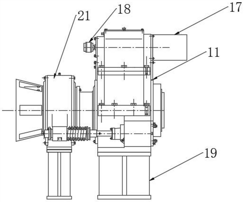
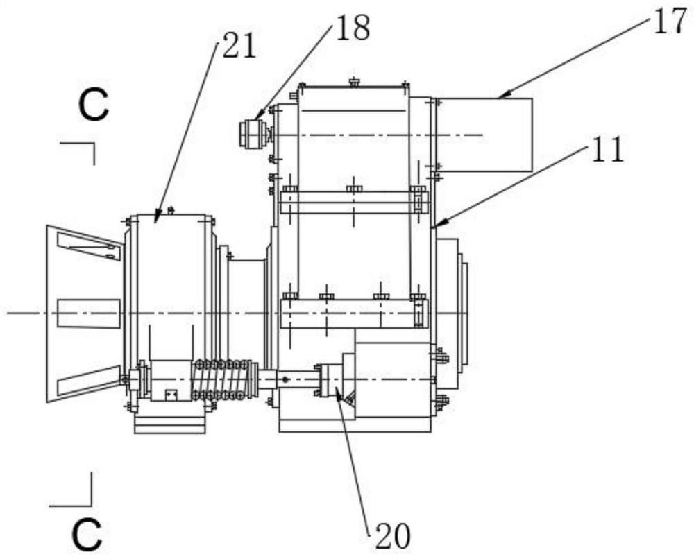
[0037] Such as Figure 1 to Figure 14 As shown, a new type of rotary feeding device for cold-rolled metal seamless pipes, including No. 1 pipe pushing mechanism 1, blanking table 2, No. 1 mandrel rotation mechanism 3, No. 2 pipe pushing mechanism 4, No. 2 Mandrel rotating mechanism 5, No. 3 pushing mechanism 6, No. 1 pipe rotating feeding mechanism 7 and No. 2 pipe rotating feeding mechanism 8, in the No. 1 mandrel rotating mechanism 3, No. 2 mandrel rotating mechanism 5, A mandrel 9 runs through the No. 1 pipe rotary feeding mechanism 7 and the No. 2 pipe rotary feeding mechanism 8;

[0038] The No. 1 tube pushing mechanism 1 includes a chain transmission mechanism and the No. 1 tube pushing trolley arranged on the chain in the chain transmission mechanism. The said chain transmission mechanism includes two brackets ...


PUM


Abstract

The invention belongs to the technical field of metal seamless pipe rolling, and in particular relates to a novel rotary feeding device for cold-rolled metal seamless pipe. Including No. 1 tube pushing mechanism, blanking table, No. 1 mandrel rotating mechanism, No. 2 pushing tube mechanism, No. 2 mandrel rotating mechanism, No. 3 pushing tube mechanism, No. 1 pipe rotary feeding mechanism and No. 2 Pipe rotation feeding mechanism, mandrels are installed through the No. 1 mandrel rotation mechanism, No. 2 mandrel rotation mechanism, No. 1 pipe rotation feeding mechanism and No. 2 pipe rotation feeding mechanism; The mandrel rotation mechanism and the No. 2 mandrel rotation mechanism realize the stable rotation of the pipe. Through the No. 1 pusher mechanism, the No. 2 pusher mechanism, the No. 3 pusher mechanism, the No. The feeding mechanism realizes the stable and continuous feeding of the pipe material, and achieves the effect of non-stop and uninterrupted rolling, and the invention has stable and reliable operation and high transmission efficiency.

Description

technical field [0001] The invention belongs to the technical field of metal seamless pipe rolling, and in particular relates to a novel rotary feeding device for cold-rolled metal seamless pipe. Background technique [0002] The metal seamless pipe cold-rolled forming process is that a suitable mandrel is built in the capillary, and the roll pass surrounds the outer diameter of the pipe blank and reciprocates along the axial direction of the pipe blank. Since it is deformed at room temperature, the metal deformation resistance is relatively large. , if the preparation method with a large amount of deformation is adopted, the rolling force will be huge, and problems such as complex equipment structure and huge mechanism will appear. In order to avoid the above phenomenon, the step-by-step, multi-pass small deformation rolling method is adopted in the cold rolling of metal pipes to reduce the size of the single-pass rolling force. Defects such as "convex edges" and "hairline...

Claims


Application Information

Patent Timeline
Patent Type & Authority Patents(China)
IPC IPC(8): B21B17/02B21B35/12B21B39/06B21B39/14B21B39/34
CPCB21B35/12B21B39/06B21B39/14B21B39/34B21B17/02
Inventor 楚志兵薛春李玉贵赵晓东桂海莲帅美荣
Owner TAIYUAN UNIVERSITY OF SCIENCE AND TECHNOLOGY
Learn More