Hardware part end face grinding clamp

A technology for end face grinding and hardware parts, which is applied in the direction of grinding workpiece supports, grinding drive devices, grinding machine parts, etc. The effect of preventing excessive heat, increasing water spray pressure, and improving grinding efficiency

Inactive Publication Date: 2021-01-15
江门市新会区司前贸易中心有限公司
View PDF0 Cites 9 Cited by
  • Summary
  • Abstract
  • Description
  • Claims
  • Application Information

AI Technical Summary

Problems solved by technology

[0003] The existing hardware parts end face grinding jig has poor fixing effect when clamping the parts, which leads to the easy sliding of the hardware parts. At the same time, the contact area between the grinding plate and the parts surface is small, which affects the grinding efficiency, and is prone to incomplete grinding. During the grinding process, due to the heat generated by the friction between the grinding plate and the accessories, the existing grinding equipment lacks a cooling device, which seriously affects the service life of the grinding plate

Method used


Image

  • Hardware part end face grinding clamp
  • Hardware part end face grinding clamp
  • Hardware part end face grinding clamp

Examples


Embodiment 1

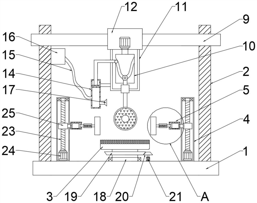
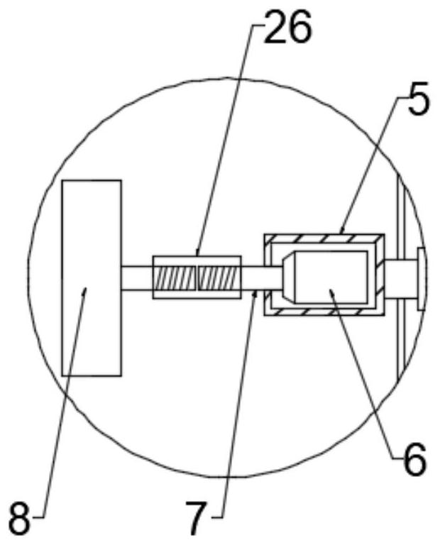
[0023] see figure 1 and 2 , in an embodiment of the present invention, a fixture for end surface grinding of hardware parts, comprising a base 1, support columns 2 are symmetrically arranged on both sides above the base 1, and a workbench 3 is arranged at the center of the base 1, and the workbench 3, mounting columns 4 are arranged on both sides, and the side of the mounting column 4 close to the workbench 3 is connected with an installation chamber 5, and a cylinder 6 is installed in the installation chamber 5, and the cylinder 6 is connected with a telescopic rod 7, and the telescopic One end of the rod 7 is connected with a fixed plate 8; a support plate 9 is fixedly installed horizontally above the support column 2, an electric slide 12 is arranged in the middle of the support plate 9, and a transmission compartment 11 is arranged below the electric slide 12, so The transmission chamber 11 is provided with a lifting device 10, a grinding plate 13 is fixedly connected to ...

Embodiment 2

[0025] In this embodiment, a rotating column 18 is connected to the bottom of the workbench 3, and a driven bevel gear 19 is installed on the rotating column 18, and a driving bevel gear 20 is meshed on one side of the driven bevel gear 19. The first driving motor 21 is connected to the bottom of the bevel gear 20, and the rotation of the first driving motor 21 drives the driving bevel gear 20 to mesh with the driven bevel gear 19, and drives the workbench 3 to rotate, which is convenient for processing different surfaces of the workpiece.

[0026] In this embodiment, an anti-slip rubber pad 22 is installed on the surface of the workbench 3 to improve the fixing effect of parts on the surface of the workbench 3 .

[0027] In this embodiment, a screw rod 23 is arranged inside the mounting column 4, a rotating motor 24 is connected to the bottom of the screw rod 23, and a lifting slider 25 is threaded on the screw rod 23, and the lifting slider 25 is The side is fixedly connecte...

Embodiment 3

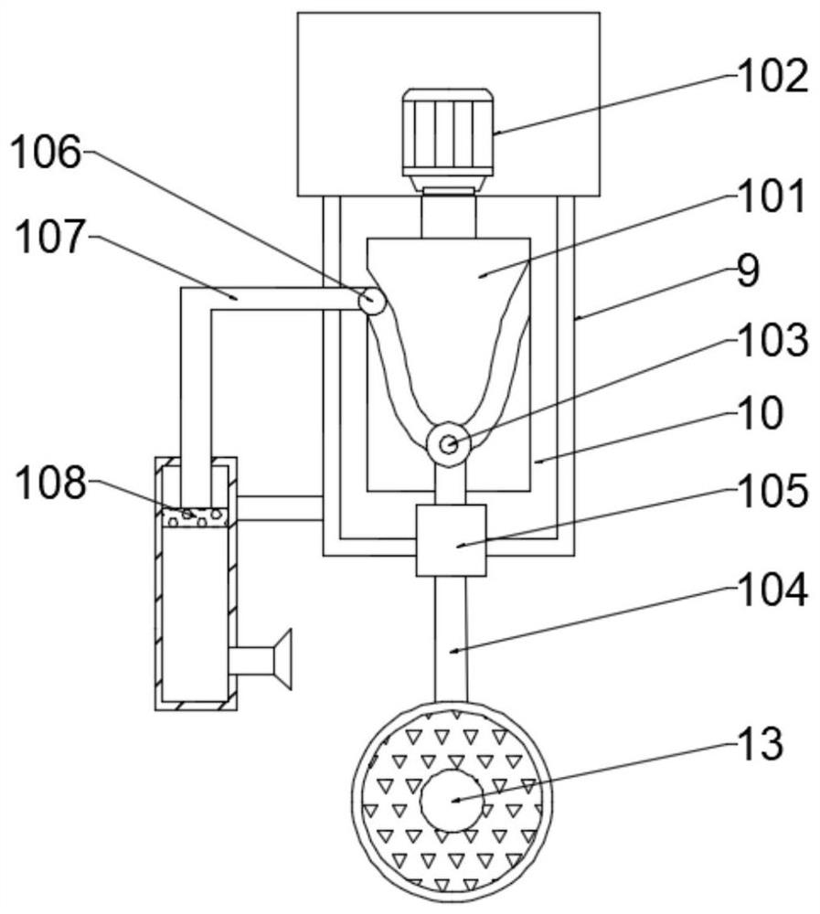
[0029] see image 3 , in this embodiment, the lifting device 10 includes a cylindrical cam 101, a second driving motor 102 is connected above the cylindrical cam 101, and a first transmission rod 103 is slidably connected in a chute on the surface of the middle part of the cylindrical cam 101, so The first transmission rod 103 is connected with a lifting rod 104, the bottom of the lifting rod 104 is connected with the grinding plate 13, and the rotation of the second driving motor 102 drives the cylindrical cam 101 to rotate. When the cylindrical cam 101 rotates, the chute on the surface and the The first transmission rod 103 cooperates to realize the up and down movement of the lifting rod 104, thereby driving the grinding plate 13 to grind up and down intermittently, which improves the grinding effect on the workpiece.

[0030] In this embodiment, a second transmission rod 106 is slidably connected to the outer chute on one side of the cylindrical cam 101, a piston rod 107 i...


PUM


Abstract

The invention relates to the technical field of hardware machining, in particular to a hardware part end face grinding clamp which comprises a base. Supporting columns are symmetrically arranged on the two sides of the upper portion of the base, a workbench is arranged in the center of the base, mounting columns are arranged on the two sides of the workbench, and mounting cavities are connected tothe sides, close to the workbench, of the mounting columns. Air cylinders are installed in the installation cavities and connected with telescopic rods, and one end of each telescopic rod is connected with a fixing plate. A supporting plate is transversely and fixedly installed at the upper portions of the supporting columns, an electric sliding base is arranged in the middle of the supporting plate, a transmission bin is arranged at the lower portion of the electric sliding base, and a lifting device is arranged in the transmission bin. According to the hardware part end face grinding clamp,a good fixing effect can be provided for hardware parts, a grinding plate can be cooled when the parts are ground, the service life of the grinding plate is prolonged, and the grinding effect of thegrinding plate on the end faces of the hardware parts is improved.

Description

technical field [0001] The invention relates to the technical field of hardware processing, in particular to a fixture for grinding end faces of hardware parts. Background technique [0002] Hardware parts refer to machine parts or components made of hardware, as well as some small hardware products. It can be used alone or as an auxiliary tool. Such as hardware tools, hardware parts, daily hardware, construction hardware and security supplies, etc. Most hardware products are not final consumer goods. Instead, it is used as ancillary products, semi-finished products, and tools used in the production process for industrial manufacturing. During the use of hardware, grinding will be carried out in accordance with the requirements of use, which is a mechanical processing method for removing materials. Refers to the processing method of using abrasives and abrasive tools to remove excess material on the workpiece. In order to ensure the stability of the grinding parts during...

Claims


Application Information

Patent Timeline
Patent Type & Authority Applications(China)
IPC IPC(8): B24B7/04B24B7/16B24B41/06B24B47/16B24B55/02
CPCB24B7/04B24B7/16B24B41/06B24B47/16B24B55/02
Inventor 梁日能
Owner 江门市新会区司前贸易中心有限公司
Why Eureka
Try Eureka